Many thanks to SWLing Post contributor, Giuseppe Morlè (IZ0GZW), who writes: Dear Thomas, I am Giuseppe Morlè, IZ0GZW, from Formia, located in central Italy along the Tyrrhenian Sea. I hope everything is going well for you after the hurricane and that you and your loved ones are in good health. I’m sending you this latest […]
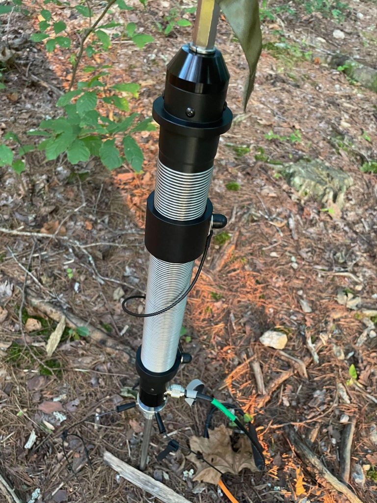
Editor note – Please enjoy this guest post from Jeff Bourgeois VE7EFF. Today, September 6, I hope to POTA activate Inonoaklin Provincial Park CA-3626 in Southern BC, Canada, located on the shores of the Lower Arrow Lakes. On this activation, I will be using my novel experimental homebrewed Coaxial-Sleeve Dipole. The results were surprising! We … Continue reading Experimental Antenna Reins-in Surprising Results→
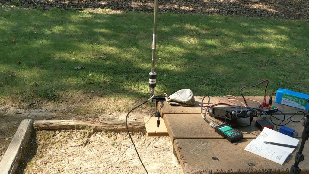
Around 10:00 this morning, Marianne looked at me and said, "So you want to go to one of those parks you were talking about?" Of course, I didn't miss a heartbeat and answered in the affirmative, so I placed the gear in the Jeep and we headed off for Keewaydin State Park, US-2088, which only a few miles down the road.
We drove to the lot where people park their boat trailers. Right next to it was a children's playground, a community pool and a very nice pavillion with plenty of picnic tables. The pavillion is all wooden, so no Faraday Cage syndrome.
I began by setting up the AlexLoop. It doesn't take long and I was on the air a few minutes before 11:00 AM - 15:00 UTC. At first, the calls came easy as I worked to really loud N9 stations out of Indiana. But after those two contacts I was calling "CQ POTA" a lot with little to show for it, and I was starting to worry that this was going to turn into a busted activation.
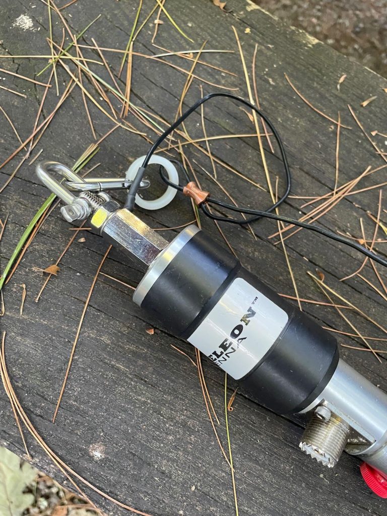
That's when I decided to break out the AX1, From previous posts you all know I've had mixed results and have been ........skeptical about its ability. I have to adnit that once I swithed over, the QSOs just started rolling in, one right after another! I worked stations in Virginia, Minnesota, Wisconsin and Oklahoma, Michigan and Ohio. I worked NL7V who according to QRZ is in Alaska, but I have to believe he was down here in the lower 48 somewhere on vacation. I didn't catch the state when he sent it. Alaska would be a dream QSO!
I didn't want to stay too long, as Marianne has no interest in Amateur Radio whatsoever. In just over a little over an hour, I made 14 contacts which is nothibg as far as POTA activations go, but still it counts as a valid activation.
The good news is that Marianne has agreed to accompany me to Krings Point State park later this week. The bad news is that since I only brought my aging Samsung tablet with me (and no laptop) my log submissions will have to wait a few days. My tablet doesn't have the display format size required to display the log upload page.
Here's the Reverse Beacon Network report for the day:
As you can see, the snr dB figures are pretty good for QRP. This AX1 is starting to turn me into a beleiver!
The rest of the day was spent doing things that Marianne had an interest in, and it turned out to be a very nice day. As we headed out to dinner this evening, we were rewarded with another gorgeous sunset.
It was a great time being back in Ottawa, visiting with friends from my old neighborhood and also spoiling my Daughters two cats.
However on the “Radio side” of things …. not so good
The plans were that I would be able (weather permitting) continue to control my hour on the Trans Provincial Net while away. It seemed that “Mother Nature” had different ideas. Most days rain or the threat of rain kept me from heading over to the park.
Above pic showing where the park was and the route I took
As I mentioned in a previous post…. there was a local (non-POTA) park within walking distance to operate from. It was a local sports field and had some bleachers for when the crowds came for Junior Soccer/Football and or Rugby…
Below pic showing how I set up at the park
Although the operating position was excellent there was NO PROTECTION from the elements which in my case meant rain.
I was able to wrap my MFJ mast to one of the bleachers and stretch the end of the EFHW antenna to the other bleacher and it did work like a charm. Signal reports were great considering I was running 50w into the antenna
So for 1 out of a potential 5 operating days it was fun and dry. Walking home with the gear safely packed in the backpack “Mother Nature” paid a short visit.
I also managed to activate CA1515 and CA1516 using my Xiegu X5105 along with a 29 foot wire (supported by the same mast mentioned earlier) with a 9:1 unun, a 17 foot counterpoise with a choke on the radio end of the coax. Jose VA3PCJ was nice enough to offer me a ride there and back. I activated the parks using SSB and VA3PCJ activated the same parks using CW and his KX3.
For Jose’s version of the park activation click HERE
I am expecting to be returning to Ottawa in Mid-January 2025 for another visit with my GrandKits and like last years winter visit there will be a car to keep me warm and dry.
We made it up here! We arrived yesterday at Alexandria Bay, NY - the land (or water) of big ships and spectacular sunsets.
Those cargo ships travel up and down the St. Lawrence Seaway, carrying tonnage betwwen the Great Lakes and the Atlantic Ocean. And as you can see, the sunsets are breathtaking.
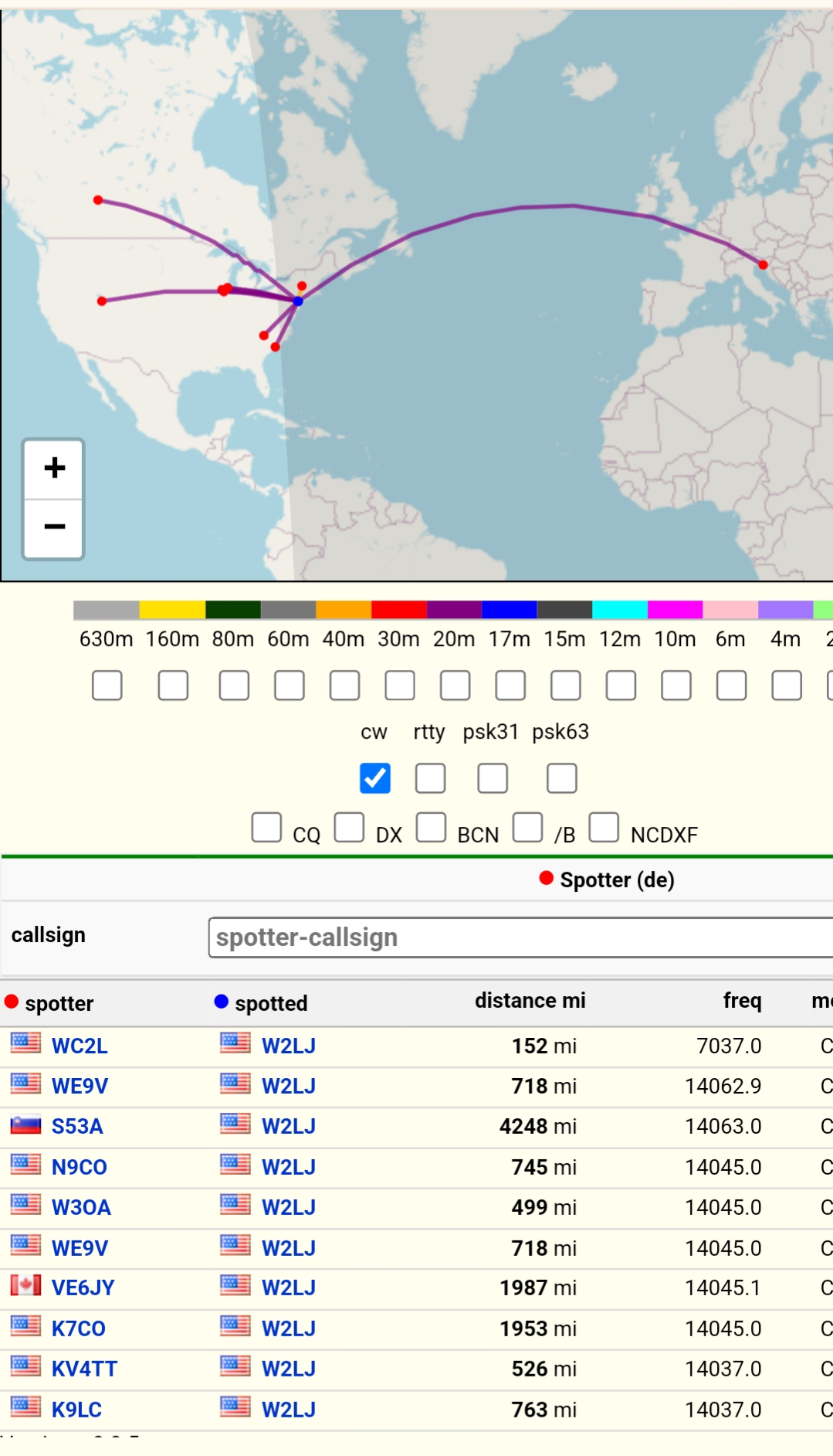
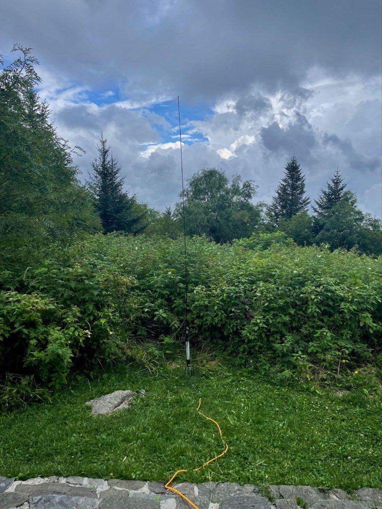
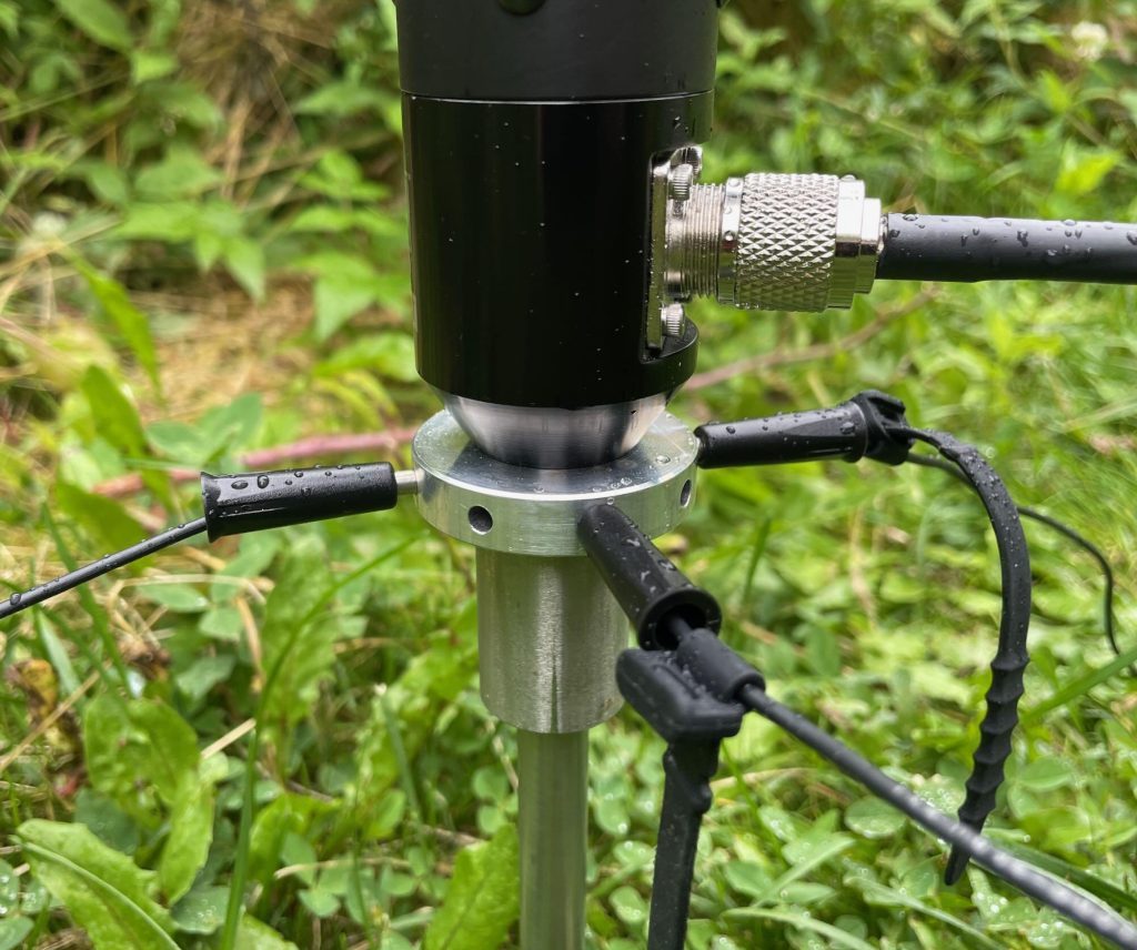
This afternoon, while Marianne took a nap, I set up the QMX and the AlexLoop on our balcony, overlooking the river. 20 Meters was a snap. I was able to get a good enough match quite easily, which kept the QMX happy. I even figured out how to get my pre-programmed messages to transmit, and I called CQ several times, just to see where the Reverse Beacon Network would pick me up, I was happy wiiith the result:
The locations of the spotters was great and the s/n db ratios were pretty darn good too. I had double digit s/n figures for a lot of the spots, indicating that I would have been heard by Hams near those skimmers.
On the other hand, 40 and 30 Meters were disappointments. I could not tune either band in well enough to keep the QMX happy. The procedure is to tune the Alex Loop's capacitor for loudest band noise. Once you do that, you're normally close enough for a decent match, No go on both 40 and 30 Meters, No matter what I did, the QMX's SWR circuitry kicked in and the unit refused to generate RF.
Luckily, the QMX is happy with the AX1, as I have previously successfully tried. That and the Buddistick will have to be the mainplayers for 40 Meters if I get the chance to do some POTAing later this week. Of course, if I decide to stick to 20 Meters solely, the Alex Loop is a more than viable alternative.
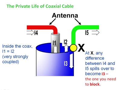
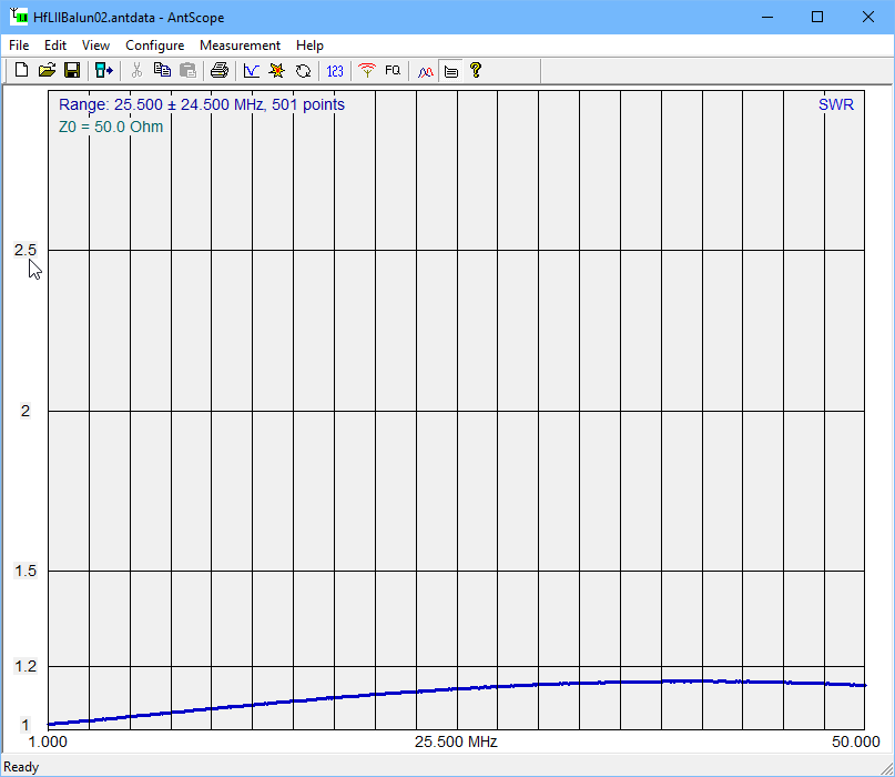
The whole thing is defined by just two currents, I1 and I2. The common mode current Ic=I1-I2. There is common mode current present in the short two wire connection to the dipole, and on the outer surface of the coaxial cable.
Note that I1, I2 and Ic are usually standing waves (ie they vary with location), and so these currents are defined here at the point where the conductors meet the end of the coax.
Are the currents measurable?
Using a clamp on RF current probe, the currents on the each of the two dipole conductors I1 and I2 is measurable, and so also the current on the outside surface of the coax shield Ic.
Remember also that these are sinusoidal AC currents, and I1, I2 and Ic refer to the magnitude of the currents.
The three currents can be resolved into the common mode and differential components, see Resolve measurement of I1, I2 and I12 into Ic and Id
(I12=Ic, the current measured with the probe around both two wire conductors or around the outside of the coax.
Can the currents be measured at an elevated dipole feed point?
Sure. I have done measurements of Ic over the length of coax by hoisting a current probe on a separate halyard to raise and lower it and reading it from the ground with a spotting scope.
Recall that Ic is usually a standing wave, and when you measure it at just one point, you don’t know much about it.
My very first posting as a trainee was to Bringelly HF receiving station in 1970. It had Rhombic antennas every 30° of the compass, and a few other antennas, but the mainstay of operation was the set of Rhombics.
The nearby transmitting station at Doonside had a similar antenna arrangement of Rhombics fed with two or four wire open transmission lines to transmitters in a central building, for most operations, no coax involved between transmitters up to 30kW and antenna feed points.
Rhombics are an example of a non-resonant antenna, these were used for a large set of operating frequencies that were not harmonically related, were changed through the day with varying ionospheric conditions over the various circuits, within the broad frequency range of the Rhombics, and not restricted by a requirement for ‘resonant length’ of radiator conductors.
You do not have to look hard for other examples of non-resonant length radiators that have good radiation efficiency.
Yet hammy Sammy thinks that ‘resonance’, whatever it means, is a necessary condition for radiation efficiency.
In this case, the quote speaks to the credibility of the author.
Social media and errors
A further disadvantage of lots of social media platforms is the inability to edit mistakes. For example, one poster wrote in the same thread:
The qualitative conclusion here is that a “wild” impedance value of 890 – j418 which is far from resonance can and does yield an acceptable SWR.
My calc is that wrt 50Ω, that example has VSWR=21.7. We all make mistakes, but this appears locked in for perpetuity.
And of course it is unsociable to call out factual error on social media.
So what happened to Bringelly and Doonside?
Bringelly part of the new western Sydney airport and Doonside is a major road interchange (the Light Horse Interchange).
It was a great time being back in Ottawa, visiting with friends from my old neighborhood and also spoiling my Daughters two cats.
However on the “Radio side” of things …. not so good
The plans were that I would be able (weather permitting) continue to control my hour on the Trans Provincial Net while away. It seemed that “Mother Nature” had different ideas. Most days rain or the threat of rain kept me from heading over to the park.
Above pic showing where the park was and the route I took
As I mentioned in a previous post…. there was a local (non-POTA) park within walking distance to operate from. It was a local sports field and had some bleachers for when the crowds came for Junior Soccer/Football and or Rugby…
Below pic showing how I set up at the park
Although the operating position was excellent there was NO PROTECTION from the elements which in my case meant rain.
I was able to wrap my MFJ mast to one of the bleachers and stretch the end of the EFHW antenna to the other bleacher and it did work like a charm. Signal reports were great considering I was running 50w into the antenna
So for 1 out of a potential 5 operating days it was fun and dry. Walking home with the gear safely packed in the backpack “Mother Nature” paid a short visit.
I also managed to activate CA1515 and CA1516 using my Xiegu X5105 along with a 29 foot wire (supported by the same mast mentioned earlier) with a 9:1 unun, a 17 foot counterpoise with a choke on the radio end of the coax. Jose VA3PCJ was nice enough to offer me a ride there and back. I activated the parks using SSB and VA3PCJ activated the same parks using CW and his KX3.
For Jose’s version of the park activation click HERE
I am expecting to be returning to Ottawa in Mid-January 2025 for another visit with my GrandKits and like last years winter visit there will be a car to keep me warm and dry.
I don’t know that I’d call Clay Mitchell, W8JNZ (SK), my mentor exactly, but I did look up to him, both as a ham and as a person. I’ll always remember one thing that he told me. “Dan,” he said, “one of the best ways to learn about something is to ‘tinker’ with it.” He’d gotten this bit of advice from Dr. Richard Crane, W8CWN, who taught physics at the University of Michigan and was a a well-known science educator and great tinkerer.
I applied this bit of wisdom to the antenna that I use for portable ops. It’s nothing fancy—just a 66-ft. doublet—but by tinkering with it over the years, it’s a much better antenna than it was when I first built it.
It started with a KX1
It all started about 20 years ago when I decided that I wanted to operate portable and bought and built an Elecraft KX-1. Out of the box, the KX1 covers 40 meters and 20 meters, and you can buy an option to add 80 meters and 30 meters to the radio. I also purchased and built the optional automatic antenna tuner.
The user manual for the KX1 antenna tuner suggested using a wire antenna of 24 – 28 feet and one or more radials of at least 1/8-wavelength. It also suggests connecting these directly to the radio without a feed line. I cut four, 24-ft. lengths of wire from a spool of wire-wrap wire that I had scavenged from the dumpster of one of my employers, purchased a BNC-binding post adapter, connected the driven element to the red binding post and the three radials to the black binding post.
The KX1 antenna featured a 24-ft. driven element and three 24-ft. radials.
The tuner found a match for this antenna, but I was never really thrilled with the performance. I made some contacts, but with only 4 watts output, most of those contacts were a struggle. I struggled with this setup for a couple of years, but since I was really enjoying portable operation, I decided that some tinkering was in order.
A new antenna is born
In 2007, my 66-ft. doublet was born. Our club here in Ann Arbor, MI, ARROW, conducts mini-Field Days the we call AMP Team meetings every month. (AMP is short for ARROW Mobile and Portable.) We haul all kinds of radio gear out to a park and set up and operate. The gear you’ll find at one of these events includes HF, VHF, UHF, and even some microwave gear. Some club members, for example, are experimenting with AREDN mesh networking, and these meetings are a good place to test out their nodes without having to worry if their node’s antenna is line-of-sight with another node.
As I was contemplating what to use for an antenna for one of these outings, I scanned the shelves in my shack for antenna-making materials. I still had a fair amount of wire-wrap wire that I could use for the antenna itself, but what to use for feed line? When my eyes lit on a spool of twisted-pair wire, I thought why not give that a try? I cut two 33-ft. lengths of wire-wrap wire for the antenna elements and one 33-ft. length of twisted-pair wire to use as feed line.
As this was going to be an experimental antenna, I didn’t care too much how kludgey the thing looked. For the center insulator, I dug a ceramic dog bone insulator out of my box of antenna parts. To connect the feed line to the antenna elements, I used a couple of small wire nuts.
Rev. A of my POTA antenna used wire-wrap wire for the elements, a ceramic dogbone insulator, and twisted-pair wire for the feed line.
Cutting a 33-ft. length of wire for the feed line was actually a mistake. I figured that if I made the twisted pair feed line a half-wavelength long, then I’d have a relatively low impedance at the rig. Instead, in my haste, I cut it too short. 33 feet is only a quarter wavelength at 40 meters, which theoretically should have yielded a high impedance at the antenna input. In practice, however, the KX-1 managed to tune that antenna and feed line on 40 meters and 20 meters just fine. That just goes to show how much I know.
To hang up the antenna, I made a small loop at the end of each wire, and to that I tied some mason twine. I threw that twine up into a tree using a weighted tennis ball, and pulled up the antenna. One problem with this approach is that I was never able to get the antenna up all that high. Sometimes the antenna was less than 15 feet off the ground.
Another problem is that it took a long time to do this. It takes time to get two lines up into trees, raise the antenna, then tie off the lines. Not to mention that you need two trees relative close to one another. Sometimes, I would set up this antenna as an inverted-V, but I still had to find an appropriate tree for this.
Enter the KX3
In 2015, I bought a used KX3. Being a KX1 user, I had subscribed to the Elecraft-KX mailing list, and when someone offered to sell a KX3 with antenna tuner for about $1,200, I jumped on it. At first, I had visions of outfitting with with a PX3 band scope and some kind of amplifier to make a base station out of it, but when I found a good deal on a Flex 6400, I decided against that approach. The KX3 would be devoted to portable operation.
Because the KX3 antenna tuner has a wider range than the KX1 antenna tuner, I wasn’t anticipating any problems with it tuning the doublet. And, in fact, that was the case. The KX3 easily tunes the doublet on all bands between 40 meters and 10 meters.
POTA improvements
Improvements to the antenna accelerated once I started operating Parks on the Air (POTA). One of the first improvements was to purchase a 10-meter, telescoping, Spiderbeam fiberglass mast. With the Spiderbeam mast, I no longer have to throw lines up into trees. I slide a small eyelet into the top section of the telescoping mast and attach the center insulator of the antenna to the eyelet. I extend the mast and operate the doublet as an inverted V. No trees needed.
To anchor the telescoping mast, I pound three garden stakes into the ground at 120-degree intervals around the mast, then put a strap around the stakes and mast to hold the mastupright. This arrangement is much easier to set up than others that I’ve seen that use ropes and tent stakes, and it is very stable. It’s certainly stable enough for a two- or three-hour POTA activation.
To anchor the elements, I use two-pound exercise weights that I bought for a buck each at a local thrift shop. Using the weights, it’s easy to extend the elements to whatever length I need quickly. Overall, setting up the antenna is very quick. I can be on the air within 20 minutes of arriving at a park.
The next improvement that I thought I’d make is to find a center insulator that would provide better strain relief for the feed line. Searching the internet, I found a 3D-printed center insulator by an eBay seller who calls himself thecrazyham. He didn’t have anything designed for a twisted-pair feed line, but I guessed that a center insulator designed for 300 Ω twinlead would work just fine. It did work just fine, and as a bonus, it only cost five dollars!
After acquiring the new center insulator, my friend, Rick, K8BMA gave me some 26-ga. Poly-STEALTH antenna wire. I cut two,33-ft. lengths and connected them to the feed line with wire nuts again. I hadn’t had any trouble with the wire-wrap wire I was using, but this wire was made with antennas in mind. It’s really first-rate stuff. I don’t think it works any better than the wire-wrap wire, but it coils up neatly and fits nicely into the small toolbox I use to carry around POTA station.
Rev. B. of my POTA antenna uses Poly-STEALTH antenna wire and a 3D-printed center insulator.
A “real” feed line
Whenever I was asked about my POTA antenna, I would brag about the twisted-pair feed line. I was rather proud that I thought to use twisted-pair wire as a feed line, and that it actually worked. But, acouple of months ago, my friend Paul, KW1L, bought a Cobra antenna. Before putting it up at his house, he asked if we could take it on a POTA activation and try it out. I agreed, and one morning, we took it up to the Island Lake Recreation Area.
Band conditions were good that morning, but even so, it seemed like the antenna was performing at least a little better than my doublet. Paul said, “Well, sure, it’s because the Cobra antenna has a real feed line.”
So, I decided to try a “real feed line” on my doublet. It just so happened that I had a 100-ft. roll of300 Ω twinlead that I purchased at a dollar store many years ago. I cut off a 35-ft. hunk of it, soldered it to the antenna elements, and put some banana plugs on the other end of it. After using thisantenna for a couple of months now, I feel that I have to swallow my pride a little and say that the antenna with the 300 Ω feed line does work a little better than it did with the twisted-pair feed line. I’m guessing that it’s because the twisted-pair feedline has a higher loss than the twinlead.
The major difference between the Rev B and this Rev C antenna is the 300-ohm twinlead feed line.
My latest improvement is to use a 4:1 balun between the feedline and the antenna tuner. Until just recently, I was connecting the feedline directly to the KX3 antenna tuner, but the fellow who sells Cobra antennas recommends using a 4:1 balun, so I thought that doing so might improve my antenna’s performance as well.
Several years ago, I purchased a couple of W1CGcurrent balun kits at a hamfest, and now was the time to build one. This is a really great kit, and if you ever see one at a hamfest or wherever, buy it. The New Jersey QRP Club that sponsored this kit is now defunct (despite the website still being online), and the kits are no longer available. (I’ve been thinking about kitting up some and selling them, but that’sa discussion for another day.) The instruction manual is still available, though, and it’s not hard to find the parts.
If you’re at all interested in baluns and how they work, you should download the instructions. They contain a great description of how baluns work and the difference between voltage baluns and current baluns.
At any rate, I built one of the kits, and have started to use the balun on my POTA activations. I can’t say for sure how much the balun has improved my results, but it certainly hasn’t hurt them, so I’m going to continue to use it.
Tinkering gets results
If you take away only one thing from this article, take away the idea that tinkering with something gets results. The antenna that I’m using today is basically the same antenna that I built 20 years ago, but the tweaks that I’ve made have significantly improved its performance and its ease of use.
One final note: I recognize that much of my success is due to the magic of the Elecraft antenna tuner. I have used this antenna with other antenna tuners, including the inexpensive Z-match tuners you can get from Ali Express or Amazon. It should also work well with the Emtech ZM-2 antenna tuner. If you purchase and tinker with this antenna and one of these tuners, please let me know how it works out for you.
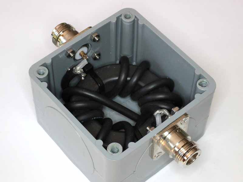
Let’s remind ourselves of the internal layout of the uncompensated balun.
The coax is quality RG58A/U with solid polythene dielectric. The coax is wound with a bending radius of about 10mm, way less than Belden’s specified minimum bending radius of 50mm.
So, the question is does this cause significant centre conductor migration that will ruin the characteristic impedance:
when it was first constructed; and
through life.
Note the pigtails at each coax connector, they are a departure from Zo of the coax and the N type connectors. They can be seen as short sections of transmission line with Zo perhaps 200Ω or more. The effect of these is to transform impedance and so cause the input VSWR to depart from ideal.
When first constructed
Above is a chart from the original construction articles. InsertionVSWR @ 30MHz is about 1.15.
Note the pigtails at each coax connector, they are a departure from Zo of the coax and connectors. They can be seen as short sections of transmission line with Zo perhaps 200Ω or more. The effect of these is to transform impedance and so cause the input VSWR to depart from ideal.
After 5 years of service
This article presents measurement of the balun 5 years after it was made, 5 years in use, but not operated at temperatures above datasheet maximum.
Above is a NanoVNA screenshot of measurement of the compensated balun using the calibration LOAD, a couple of SMA(F)-N(M) adapters and a short SMA(M)-SMA(M) cable.
InsertionVSWR is highest at 1.01 @ 16MHz, at the limits of accuracy with this equipment. These 3kV 10pF ceramic capacitors have measured Q around 500 at 30MHz, expected loss is less than 200mW @ 1kW through.
The InsertionVSWR is not significantly affected by the quite small bending radius.
Voltage withstand
Does tight bending of this cable degrade voltage withstand of the balun?
Experience Hipot testing lots of baluns with this type of coax winding shows that the voltage withstand weakness is over the surface of the dielectric from braid to centre conductor, and pigtails of less than 15mm will flash over before internal flashover.
Alternative coax types
Coax with a solid PTFE dielectric is more suitable as the dielectric is harder and withstands higher temperatures before deformation.
Foamed dielectric cables are much more prone to migration of the centre conductor on tight bends, even at room temperature and are probably unsuitable for tight wraps.
Small diameter cables might seem the obvious answer, but they are higher in loss and will run at higher temperature.
Conclusions
Though the coax bend radius is substantially smaller than specification minimum bend radius:
when first constructed, there was little evidence that the coax characteristic impedance was altered by the winding radius, and that the pigtails were the main contribution to InsertionVSWR; and
after five years of service, the InsertionVSWR of the compensated balun is excellent, at the limits of accuracy of the test equipment and again, little evidence that the coax characteristic impedance was altered by the winding radius.
Solid dielectric coax may be quite satisfactory at static tight bend radius, subject to the temperature of operation and applied forces.
Whether you’re a seasoned ham or buying your first antenna, choosing the right one is more about how you operate as an individual and less about the antenna’s capabilities. In previous OnAllBands articles, I’ve explored field antennas and the decision-making process behind choosing the right one. I believe that a practical understanding of your operating style is key to making the best choice.
This article is about vertical antennas—specifically, those designed to be portable and stealthy. These antennas are ideal for field operations like POTA, SOTA, or IOTA, and for those living under HOA restrictions that prohibit permanent antennas.
(Image/Thomas Witherspoon, K4SWL)
There are hundreds of vertical antennas on the market, and it’s beyond the scope of this post to cover them all. Instead, I’ll focus on three models I’ve personally used, each representing different concepts and reasons why you might choose one over another.
All of these antennas are multi-band, and while some can be installed permanently with proper sealing, they are primarily designed with portability and ease of setup in mind.
Before diving into the specifics, consider these questions as you search for your next antenna:
What modes and power levels do you intend to operate? Ensure your antenna can handle the wattage and duty cycle of your chosen mode (SSB, CW, Digital). For example, an antenna that handles 100 watts SSB may not be suitable for 100 watts FT8.
What bands do you plan to operate? Confirm that the antenna covers your preferred bands. Portable verticals are effective on 20 meters and above but become less efficient at lower frequencies due to the need for loading coils to electrically lengthen the radiating element. This compromises performance and decreases operating bandwidth. However, I’ve had great success on 80 meters with some portable verticals, though they are less efficient compared to longer wire antennas.
How far do you plan to hike with this antenna? Check the specifications for weight and element lengths, as these factors will impact your comfort and the feasibility of carrying it in your pack.
How important is frequency agility? If you primarily operate FT8 and stay on one frequency for extended periods, any antenna will likely suffice. If you frequently move across bands to chase activators or DX, consider an antenna that doesn’t require manual tuning.
***
Three Types of Portable Verticals
Here are three vertical antennas I’ve used in the field, along with their pros and cons:
***
1. Quarter Wave Verticals
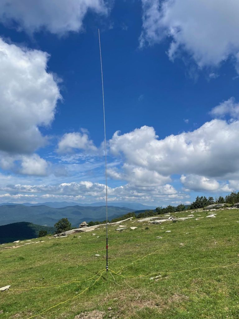
One of the simplest vertical antennas is the quarter wave. My first quarter wave antenna was a 5-meter radiator wire (one-quarter the length of 20 meters) with four counterpoise wires on the ground. I attached the radiator to the center of my coax and the counterpoises to the shield. I’ve deployed the radiator vertically in a tree (great for permanent setups) and supported it with a fiberglass telescoping fishing pole (ideal for portable use).
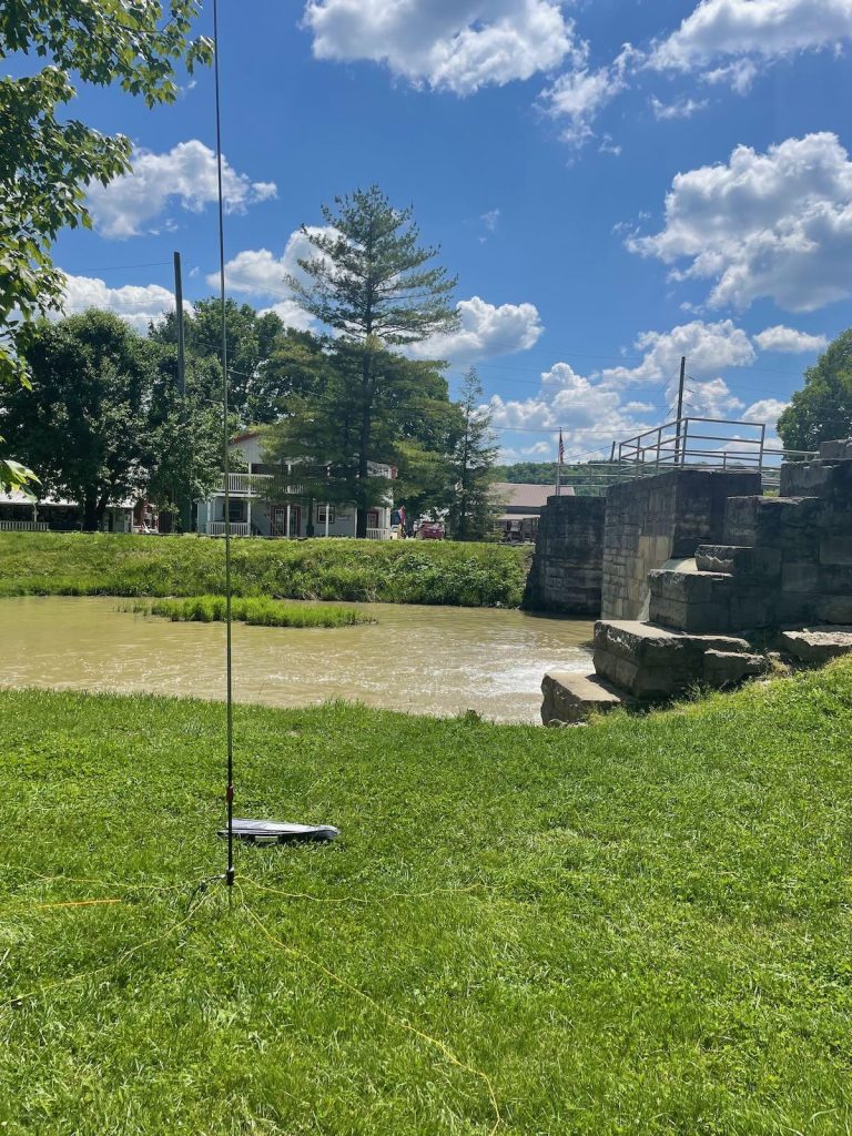
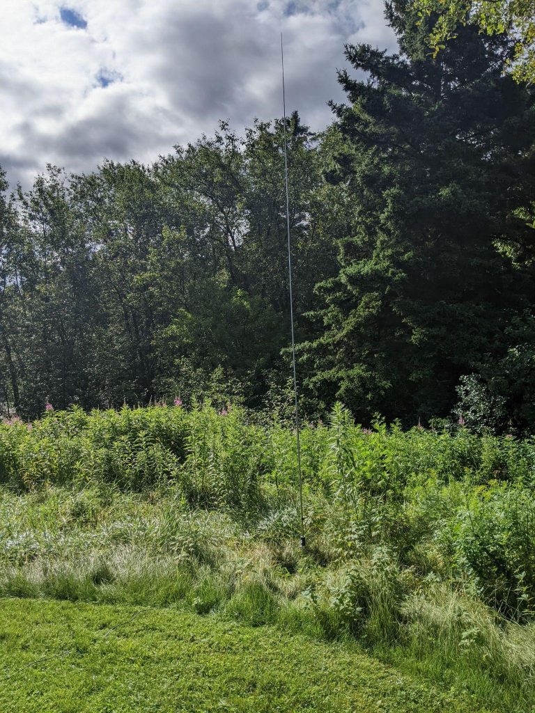
While these antennas are simple to build, I prefer an antenna that works on multiple bands and is easy to deploy and pack. This is why I’m a big fan of the Chelegance MC-750.
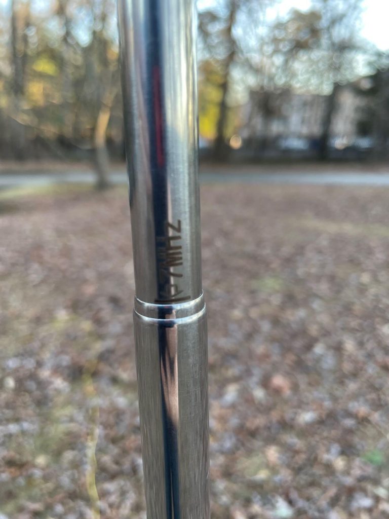
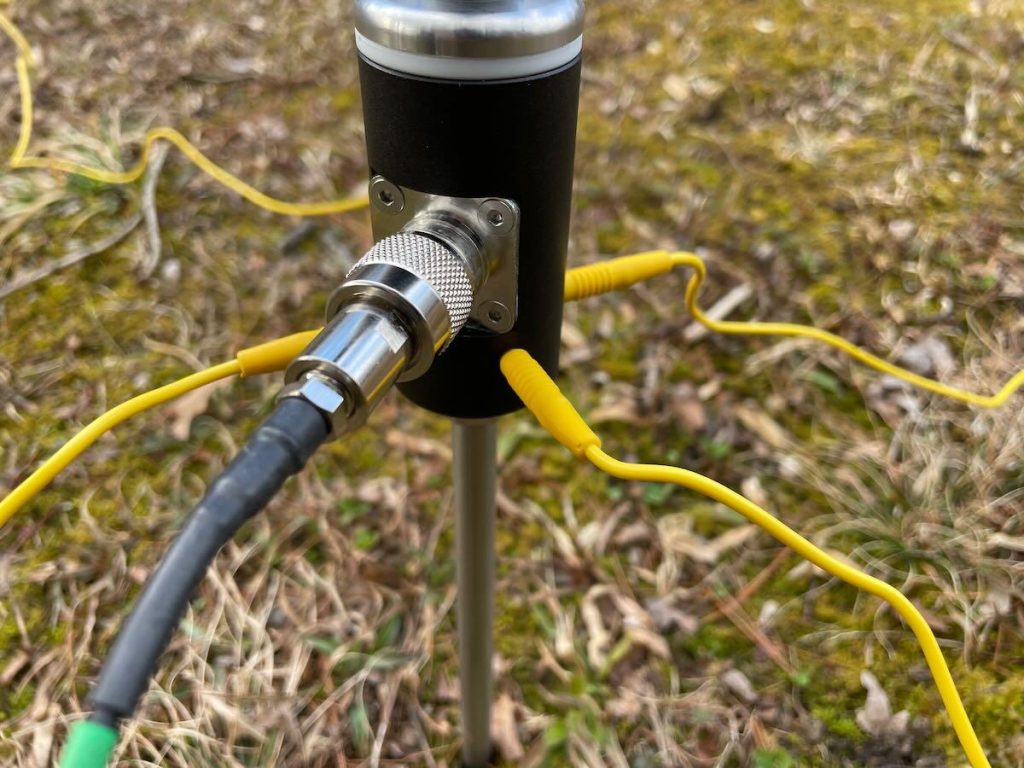
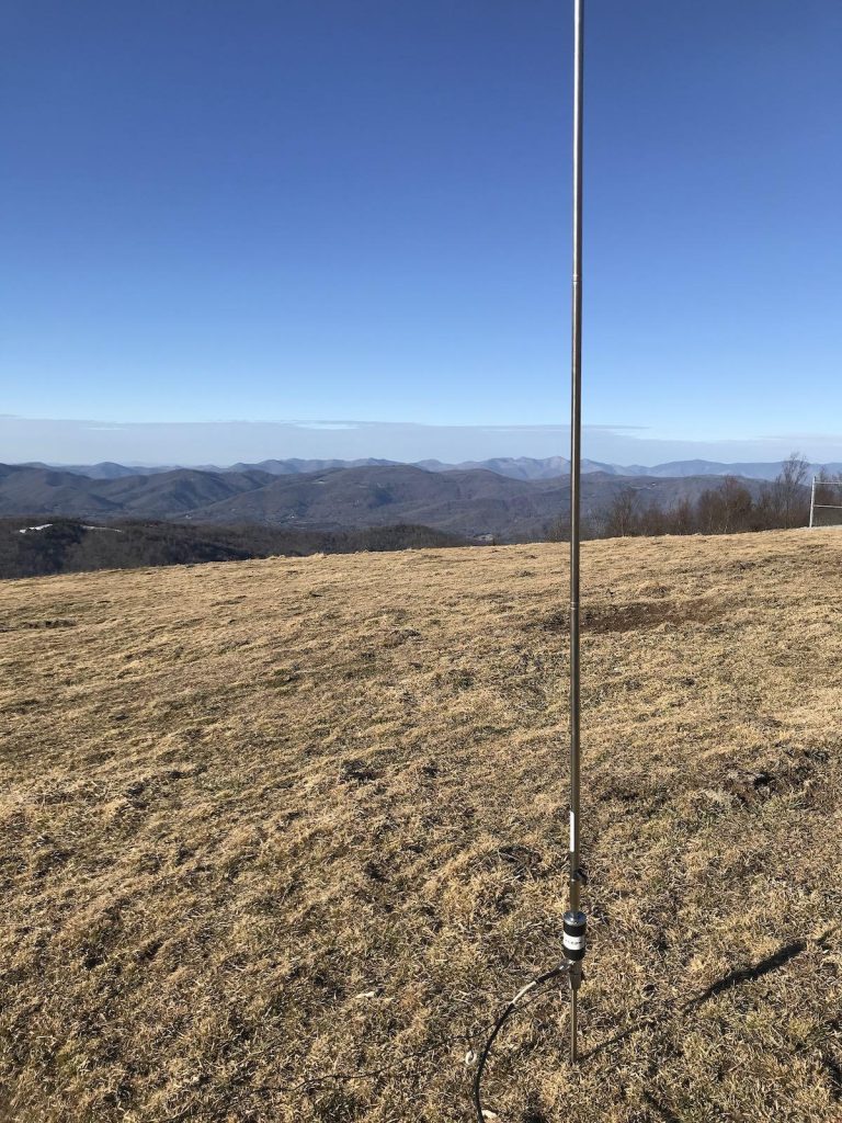
The MC-750 is a portable vertical deployed using either a stainless ground spike or a tripod. The vertical element is a stainless steel whip with silk-screen markings that help you deploy the antenna for resonance on multiple bands.
(Image/Thomas Witherspoon, K4SWL)
When I follow the silk-screen markings and all four counterpoise wires (attached to the base), I consistently achieve a near 1:1 SWR. Thus, no ATU is needed. The SWR remains consistent across various topographies.
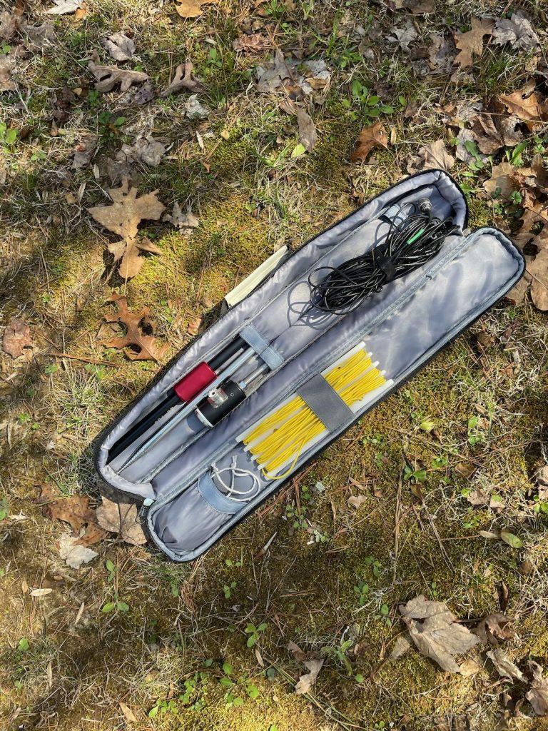
The Chelegance MC-750 comes with jacks to install four included preassembled counterpoise radials. (Image/Thomas Witherspoon, K4SWL)Chelegance MC-750 carrying case (Image/Thomas Witherspoon, K4SWL)
The MC-750 ships with a coil for 40 meters. Chelegance also offers an optional 80 meter coil as well.
Pros: Easy deployment, high quality, efficient, multi-band use with no ATU needed, resonates on 20-10 meters and 40/80 meters with coils, comes with a custom padded carrying case.
Cons: Not truly a con, but you must adjust the whip length when changing bands if not using an ATU.
***
2. Verticals with Transformers
Chameleon CHA MPAS Lite Modular Portable Antenna (Image/Thomas Witherspoon, K4SWL)
If you regularly use an antenna tuner in the field, you might prefer a high-quality multi-band vertical antenna equipped with a transformer to reduce potentially high impedances to a level manageable by most tuners. I think of this type of antenna as the vertical equivalent of a random wire antenna. Many of my QRP transceivers have internal ATUs, making this type of antenna very appealing. The one I have the most experience with is the Chameleon CHA MPAS Lite.
Like the MC-750, the MPAS Lite uses a stainless steel whip but includes a transformer at the base, making it easier to match the antenna across multiple bands with virtually any ATU. Additionally, it can operate on lower bands, including 80 meters, without needing a loading coil attached. While not as efficient below 30 meters, it remains highly effective for both POTA and SOTA where you are often the DX.
The MPAS Lite offers excellent frequency agility, which is a major advantage if you frequently hunt or chase other stations in the field. Just change the frequency, activate the ATU, and you’re set.
(Image/Thomas Witherspoon, K4SWL)
The MPAS antenna can also be configured as an end-fed random wire using the counterpoise wire. Consult the MPAS Lite manual for multiple configurations.
Pros: Easy deployment, high quality, multi-band use, frequency agility, only one counterpoise, versatile platform for multiple antenna configurations.
Cons: Pricier than the MC-750.
***
3. Loading Coil Verticals
I’ve used several antennas with helically wound coils and a sliding tuning coupler at the base to match the antenna across multiple bands. The coil at the base shortens the antenna electrically, making it portable and low profile—ideal for stealthy use or in neighborhoods with aggressive HOA restrictions.
Among the many coil antennas available, the new REZ Antenna Systems Ranger 80stands out for its robustness. I was impressed with its ease of setup, high quality, and smooth tuning coupler. The REZ Ranger 80 antenna also handles higher power than other coil systems—100 watts CW/digital and 200 watts SSB.
REZ Antenna Systems Ranger 80 HF Portable Antenna System (Image/Thomas Witherspoon, K4SWL)(Image/Thomas Witherspoon, K4SWL)
The Ranger 80 is quick to deploy and incredibly durable. While I’ve never been a big fan of verticals with loading coils and sliding tuning couplers, as they can be finicky to tune, I found the REZ Ranger 80 to be the best of the bunch and more forgiving than others I’ve used.
(Image/Thomas Witherspoon, K4SWL)
Pros: Easy deployment, superb quality, higher power handling capacity, multi-band resonance, no ATU required.
Cons: Heavier than other options, tuning coupler needs adjustment for each band change, pricey.
***
Summary
Choosing the right portable vertical antenna is more about matching your equipment to your specific operating style than simply selecting the most capable model. Whether you prioritize ease of deployment, frequency agility, or power handling, the antennas discussed—like the Chelegance MC-750, Chameleon CHA MPAS Lite, and the REZ Ranger 80—offer distinct advantages that cater to different needs.
Before making your decision, consider the nature of your operations. Are you regularly chasing signals across multiple bands, or do you prefer to set up and stay on one frequency? Do you need a lightweight, portable solution for long hikes, or are you more concerned with stealth and ease of use in restricted environments? Your answers will guide you to the right antenna.
Ultimately, the best antenna is the one that enhances your enjoyment of the hobby, allowing you to operate confidently and efficiently in your chosen environment. If possible, try before you buy—borrowing from friends or club members can provide valuable insights that specs alone can’t offer.
It was busy, but at the same time productive. Saturday started off with the monthly ETS of NJ VE Session. We had three candidates and only three VEs. I can't tell you the last time that happened as the number of VEs that show up usually way outnumbers the candidates! In fact, I was sweating it out for a while worrying that I would have to tell the candidates that for lack of VEs, they'd have to go home.. Fortunately, a third showed up and we were fine.
We brought one new Tech into the fold and another Tech upgraded to General. The third candidate walked away with nothing, which was extremely disappointing to both him and us. He was a Tech who let his license lapse in 2012. He took the exam and I don't know if it was a case of overconfidence or if he just hurried too fast through the last 10 - 15 questions. He was going great guns, but in that last set of questions, he got enough wrong to put him two over.
I hate when that happens! I offered him the chance to take another version, but he declined. Hopefully, we'll see him again next month after a bit more study. He was so close, I'd hate to see him give up in disgust!
The rest of Saturday was spent doing house chores as on Sunday morning, we had a guest arrive for a visit for this week:
My sister and brother-in-law went down to the Jersey Shore for the week and the AirBnB they are staying at does not allow pets, so Jessie (Harold's "cousin", and also a rescue) has come to stay with us for the week. She took an immediate liking to our son, Joseph as you can see in the photo. She's a good girl, very quiet and very friendly - she loves to be held. A real Momma's girl. She's a demon with her food, though! I put the kibble she eats in her bowl and all I did was blink and it was gone! LOL! Maybe my sister should have named her Hoover!
That reminds me of a story. When I was young, one of the first "real" jobs I had (not working at my Dad's store) was working at a camera store. If you've ever worked retail, you know that when it comes to lunch and eating - you eat fast; or you don't eat at all. It got to be such a bad habit, that when I was eating a meal at home, my Mom would always say, "Larry, take human bites!"
Anyway, getting back on track, in between grocery shopping and cleaning, I did manage to get down to the shack to sneak in a few POTA stations. Geomagnetic activity was quite high on Saturday with the K index getting up to 5 for a bit, but I still managed to work a couple, even though signals were down in the mud.
On Sunday, I finally managed to do something that I've been wanting to do the past few weekends. I finally got the chance to try out my KM4CFT EFRW antenna. I wanted to give it a workout before I put the heat shrink over the UNUN circuit board. Again, due to a prior obligation in the afternoon, I only got a few hours in, but I have to say that I am pleased with its performance.
For starters I called CQ on both 40 and 20 Meters - about maybe a 1/2 dozen times on each band, just to see where the Reverse Beacon Network would pick me up:
Not too shabby! Not the greatest signal strengths on 20 Meters, but I was having a hard time getting the Emtech ZM-2's red LED to go out. So later in the afternoon, I switched it out for my 4 States NM0S tuner.
This little guy worked like a champ! I was able to get the red LED to go out completely and the green LED to glow like there was no tomorrow. I promptly worked several POTA stations, including Dan KB6NU - fellow blogger, who you see on the blog roll to the right so often.
I think I'm going to have to open and inspect the connections inside the ZM-2. as it has always worked reliably for me in the past. Even so, this was the tuner I keep in the shack for when I fire up my HW-8. I may purchase another of these to keep in the QMX bag. And speaking of the QMX, I'm getting to the point where it's becoming more routine to operate without having to pause to think what do I have to press in order to............... It's slowly becoming second nature but I still have a ways to go.
I was happy with the KM4CFT, and I was happy with the 4 States tuner and the QMX. Like I said, it was a productive weekend.
Last thing - something I saw on Facebook on the EFHW Antenna page that was posted by K4IVN. I am guessing he fabricated this via his 3D printer:
This will hold his UNUN and at the same time it has a spool for the wire of his EFHW or EFRW. How neat is this? I don't know if he fabricated a cover to keep the UNUN safe from the elements, but I'm guessing he either has, or will do do.
Another project for me - to make one of those daisy wire spools like the ones Dave KD2FSI made for me so I can better store the KM4CFT EFRW.
I meet up with Chris, N9CVR, of The Ham Radio Experience. He shows off his fishing pole vertical antenna and we use it to catch some contacts along the Wolf River at the Mukwa State Wildlife Area, (POTA US-4314).
It’s hard to keep up with all the new amateur radio gear you’ll find at DX Engineering! The latest products from leading manufacturers are being added weekly to the 30,000-plus ham radio items—from more than 175 top amateur radio providers—available at DXEngineering.com.
OnAllBands is dedicated to making sure you’re not missing out on that station addition that will improve your contesting scores, help you work more DX, upgrade your emergency preparedness, and enhance your 0verall enjoyment of the world’s greatest hobby.
DX Engineering has you covered with a bunch of new products you’ll want to add to your amateur radio must-have list, from premade coax assemblies to a new Icom handheld receiver. DX Engineering’s Michael Murphy, KI8R, highlights a few of the latest offerings in the video below.
Like what you see? Click on the links below for all the details.
This livestream recording is from September 1, 2024 – the NW7US Radio Communications Channel Livestream. We do this livestream every Sunday at 21:15 UTC. Here is the link to the livestream from this past Sunday: The livestream list is here: https://www.youtube.com/@nw7us/streams I hope to see you in our livestream live chat, during the next session […]
This livestream recording is from September 1, 2024 – the NW7US Radio Communications Channel Livestream. We do this livestream every Sunday at 21:15 UTC. Here is the link to the livestream from this past Sunday: The livestream list is here: https://www.youtube.com/@nw7us/streams I hope to see you in our livestream live chat, during the next session […]
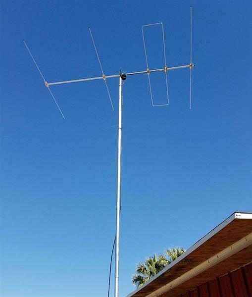
The 6 meter band is hot in the summer time and there is no better way to exploit it than with a directional antenna like the 6 meter Moxon. The Moxon is a 2 element Yagi that is inexpensive and easy to build, but also offers great results with 5.5dbi of gain and a 25db front to back ratio
The Moxon is named after its creator Les Moxon, G6XN. It is best described as a rectangular two element Yagi antenna. I said rectangular as the ends of the driven element and the reflector are folded inwards, which reduces the amount of space it occupies, about 70% of the space of an equivalent dipole antenna. If you add lightweight spanners to the rectangle, you can rotate the antenna.
Typically, a 6 meter Moxon will have about 5.5dbi of forward gain, and exhibit a high front to back ratio, up to 25 dbi when elevated to the optimal height of about 18 feet. They also have a 50 ohm impedance at the feed point, so no matching network is required, which simplifies their construction.
To make this project more approachable, three of the parts are 3D printed, the hub, hub adapter, and feed point mount. I used PLA+ to print these parts. This is ok for temporary use, but if you are thinking of permanently mounting this antenna, I’d use something more weather resistant like Petg or ASA. All of my 3D printed parts are available on Thingaverse if you want to tackle this project yourself.
The KB9VBR 6 Meter Moxon Antenna Parts list: 4 – 48 inch x 3×8 inch fiberglass fence posts 1 – 3D printed Moxon hub 1 – 3D printed hub adapter 1 – 3D printed Feedpoint center SO-239 chassis connector 20 feet 20 or 22 ga wire 6 x ½ inch machine screws, nuts, and washers 8 small Ring terminals String trimmer line Painters pole: 15 – 23 feet
Mike K8MRD from Ham Radio Tube just posted this video on You Tube and if you own a Xiegu X5105 you gotta give this a try. I will be looking for the the MFJ Antennas he mentioned at any hamfests I get to.