Parks on the Air (POTA) has taken the ham radio community by storm. According to POTA’s website, there are more than half a million unique “hunter” call signs participating in this volunteer program that was “first inspired by the outstanding work of Sean Kutzko, KX9X, and Norm Fusaro, W3IZ, from the American Radio Relay League in 2016.”
The POTA phenomenon sprung from the ARRL’s one-year National Parks on the Air program, which gave legs to today’s soaring interest in park activations. Earlier programs such as Ohio State Parks on the Air, which celebrated its 17th year in September 2024, provided inspiration and operating details for the National Parks event.
As of this posting, the list of available POTA locations includes 11,668 parks in the U.S., 5,915 in Canada, and 8,523 in Australia, with new spots being added weekly. At any given time, scores of parks around the world—from North Carolina’s Blue Ridge National Parkway to Sweden’s Kungsbro Nature Reserve—are ripe for keen park hunters (click here to see what parks are on the air right now).
Since its founding, Parks on the Air has captured the imagination of young and seasoned operators, both park activators and hunters, to the tune of several million QSOs. Activators have embraced both the challenges and sheer enjoyment of making contacts amidst views you simply can’t get from inside a shack:
(Image/Thomas Witherspoon, K4SWL)
“Parks on the Air combines a few of my favorite things—ham radio, the outdoors, and, if the conditions are right, the occasional pileup,” DX Engineering’s John Miller, KJ3X, told OnAllBands back in 2019 when the program was getting its foothold.
“Parks on the Air brings publicity to amateur radio, and amateur radio brings publicity to parks that normally might be overlooked. I’ve made contacts with people who never knew a particular park existed and have since visited that location.”
Jeff, KB8ZWT, DX Engineering customer/technical support specialist, during his first POTA activation in 2019. He used a Chameleon MPAS portable antenna system during his activation at West Branch State Park in Portage County, Ohio. (Image/Jeff, KB8ZWT)
POTA Resources
The ARRL’s 144-page reference guide, “The Parks on the Air Book“, is an excellent source to launch your POTA pursuits. Available at DXEngineering.com., the paperback features a look at how 14 operators, representing a range of skill levels and backgrounds, set up and handle their park activations, including gear lists of each. The book also covers satellite operating, QRP, urban backpack portable, wire antennas for POTA, and more.
“Just a very informative book,” in the words of one customer.
Still not convinced to add POTA to your list of ham radio activities? OnAllBands put together the following list.
10 Reasons to Give POTA a Try
POTA activations are an easy way to hold your own mini-DXpedition. Ever wanted to be a station in demand without having to traipse halfway around the globe? POTA is your answer.
It doesn’t require a mega-station to make contacts. For a modest investment you can start making QSOs from a park on day one.
With thousands of qualified sites, finding one within a reasonable driving distance shouldn’t be too difficult (this, of course, depends on where you live). How about picking a new spot every couple of months for a weekend getaway with the family or significant other?
While you may experience pileups, it’s still low pressure. Handle what you can based on your capabilities and improve your skills the more activations you take on.
Even if you don’t set the airwaves on fire, you’ll get to enjoy the foliage, an infusion of vitamin D, and perhaps some curious wildlife observing you from behind a tree.
Become an ambassador for ham radio. “Hey, what’s all this stuff you’ve got here? Looks like a blast,” someone—or perhaps dozens of folks—will undoubtedly inquire. It’s your chance to show them (without overdoing it) why ham radio is the greatest hobby in the world.
Like a personal Field Day adventure every time you set up, POTA is a great opportunity to experiment with a new antenna, QRP operation, and alternative power sources as you free yourself from the confines of the shack.
It will help you become a better operator, especially from an EMCOMM perspective. From the POTA website, the program is meant to encourage “amateur radio operations that promote emergency awareness and communications from national/federal and state/provincial level parks.”
The best reason of all—POTA operations are fun. After all, isn’t that why you spend hours thinking about refining your stations, getting on the air, and filling your logbooks?
In addition to “The Parks on the Air Book”, DX Engineering carries the gamut of POTA-friendly gear you’ll need to assemble the portable station that best fits your goals and budget, including:
In the video below, DX Engineering’s Michael Murphy, KI8R, with help from the active community of microwave operators and assistance provided by rain scatter propagation, makes two QSOs on 10 GHz—his first ever on the super high frequency bands.
You can watch both QSOs in action on the IC-905, along with tips on parabolic antenna positioning to maximize your receive signal, more about rain scatter, and some encouraging words on expanding your amateur radio horizons by giving these lesser-used bands a try.
“In the 40 years I’ve been in this hobby, this is probably one of the most awesome things I’ve ever done in ham radio,” KI8R said.
While contesters the world over await the SSB portion of the CQ World Wide DX Contest at the end of the month, don’t forget that there’s plenty to do on the air leading up to this mega-event.
Sis-Boom-Bah
With college football frenzy in the air, we’d like to give a special shout out to collegiate competitors this October who will be more concerned with hamming than pigskins…gray lines than goal lines…station grounding than intentional grounding. All of us at OnAllBands wish the best of luck to the students, faculty, and alumni who will be participating in the Collegiate QSO Party October 5, 0000Z to October 6, 2359Z.
From the contest website, “The Collegiate QSO Party is an operating event focused on amateur radio clubs at colleges and universities around the world. Each Fall, the Collegiate QSO Party provides an opportunity for clubs to demonstrate amateur radio to new members, engage with alumni, and promote activity throughout college and university communities.”
This year’s roster of competitors who will be trying to mitigate interference (a 15-yard penalty in the gridiron world, but even a bigger annoyance in radiosport!) includes teams from Missouri University of Science and Technology, University of Central Florida, University of South Florida, University of Florida, Milwaukee School of Engineering, Oregon State University, Michigan State University, Virginia Tech, St. Louis University, University of Cincinnati, Irvine Valley College, and others.
“This event is open to all radio amateurs,” per the event’s website. “Points can be earned by individuals, clubs, and collegiate stations. The Collegiate QSO Party encourages alumni to connect with their alma mater and students to network with other schools. New hams are welcome and stations are encouraged to be accommodating to new radio amateurs.”
A Halloween Reminder: Beware of the Wouff-Hong!
In this season of ghosts, goblins, and things that go kerchunk in the night, it behooves contesters everywhere to be wary of the most sinister, medieval —and, frankly, hilarious—of all ham radio legends. Of course we could only be referring to the dreaded Wouff-Hong—a device imagined (with tongue firmly in cheek) by Hiram Percy Maxim, W1AW, to remind amateurs that shoddy operating that runs afoul of accepted etiquette should not be tolerated.
While the first article about the Wouff-Hong, penned by The Old Man himself, appeared 100 years ago, its relevance today in light of DQRMers and other ne’er-do-wells hasn’t waned.
If you’re looking for something to do on Halloween that doesn’t involve dressing in blue tights and a cape, the Anoka County Radio Club of Anoka, Minnesota, is hosting a Halloween Special Event Station, W0YFZ, October 31, 1400Z-2000Z, 14.250 7.250 7.056 ft8.
Anoka—a northern suburb of the Twin Cities—“is believed to be the first city in the United States to put on a Halloween celebration to divert its youngsters from Halloween pranks,” according to anokahalloween.com. Today, its 17,000 residents proudly call their hometown “The Halloween Capital of the World®.”
The town’s first Halloween celebration was in 1920. The good-natured merriment lives on today with parades and other activities, including the special event station: “Anoka residents can watch their grandchildren or great-grandchildren continue the tradition they started so many years ago,” per the website.
***
Sufficiently scared? Make October the month you shake off your “mic fright,” get on the air, and make some QSOs. Here are a few contests to put on your calendar:
Oceania DX Contest, Phone: October 5, 0600Z to October 6, 0600Z. The CW portion of the contest runs from October 12, 0600Z to October 13, 0600Z. The contest promotes HF contacts to and from stations in the Oceania region as well as contacts between stations in Oceania. Find complete rules here.
The Oceania DX Contest website offers these words of encouragement to get on the air: “This is the 79th running of the Oceania DX Contest, and with the solar conditions the way they are, we are expecting some big things from all of our contestants this year! Solar conditions are the best they have been in more than a decade, so your opportunity to make contact with stations in Oceania has never been better! We look forward to seeing you all on the air on both weekends and expect many stations from Oceania to be calling CQ Contest looking for your calls!”
QRP ARCI Fall QSO Party: October 12, 0000Z to 2359Z. The QRP Amateur Radio Club International kicks off autumn in their usual manner—by doing more with less! This club for low-power enthusiasts worldwide sponsors various contests and events that promote QRP operating and related activities, such as building minimalist radios, portable ops, and antenna experimentation. Like much of the club’s activities, its Fall QSO Party (HF CW only) is a test of ingenuity and skill, as operators make QSOs using anywhere from 55 mW or less to 5W.
Stew Perry Topband Challenge: October 19, 1500Z to October 20, 1500Z. Here’s a popular event 160M fans won’t want to miss. Point value of QSOs depends on the distance between the two stations. Participants are given one point plus another point for each 500km of distance. Points are also multiplied for lower power categories—for both the sending and receiving station. Looking to boost your top band capabilities? Read this article on the effectiveness of the DX Engineering 160M THUNDERBOLT Vertical Antenna.
ARRL’s EME—50 to 1296 MHz: October 19, 0000Z to October 20, 2359Z. Work as many amateur stations as possible via the earth-moon-earth path on designated frequencies. This portion of the ARRL EME event continues on November 16-17.
ARRL School Club Roundup: October 21, 1300Z to October 25, 2359Z. This bi-annual event is designed to foster contacts with and among school radio clubs. Participants can exchange QSO information with any amateur radio station, so non-school clubs and individuals are encouraged to participate as well. All amateur bands except 60, 30, 17, and 12 meters are permitted.
CQ Worldwide DX Contest, SSB: October 26, 0000Z to October 27, 2359Z. This is why they call this time of year Contesting Season! The CQ Worldwide DX Contest is the largest amateur radio contest in the world with over 35,000 participants. The challenge is to make as many contacts with as many DXCC entities and CQ Zones as possible, while competing against the world’s elite contesters. Not into SSB? The CW portion of the contest is November 23-24.
Also check out these State QSO Parties:
California: October 5, 1600Z to October 6, 2200Z
Nevada: October 12, 0300Z to October 13, 2100Z
Arizona: October 12, 1500Z to October 13, 0500Z
Pennsylvania: October 12, 1600Z to October 13, 0400Z, and October 13, 1300Z to 2200Z
South Dakota: October 12, 1800Z to October 13, 1800Z
New York: October 19, 1400Z to October 20, 0200Z
Illinois: October 20, 1700Z to October 21, 0100Z
***
Ready to upgrade your station for better contesting results? Visit DXEngineering.com for everything you could possibly need to boost your scores:
The TO2DX DXpedition from Réunion by OM2DX is scheduled to run until October 7 from this overseas department and region of France in the Indian Ocean, 422 miles east of Madagascar. The HF operation from the 970-square-mile island (slightly smaller than Rhode Island) is scheduled to be active on CW, FT8, and RTTY. TO2DX, operating from the island’s far west side in the commune of St.-Paul, was QRV for the just-completed CQ WW DX RTTY Contest.
The volcanic island of Réunion (part of the Mascarene Islands) is the 219thMost-Wanted DXCC Entity per Clublog as of September. Originally named Bourbon, Réunion has a population of around 885,000 and is home to a rich diversity of flora and fauna. There are more than 230 plants only found on the island, as well as endemic birds such as the Réunion cuckooshrike, which, if you’re lucky, can be observed in two mountain forests in the northern part of Réunion. The island’s marine biodiversity is even more impressive. Its waters feature 1,000-plus species of fish and 500 crustaceans. You’ll also find a variety of shark species, whales, and sea turtles.
QSL Cards
The active hams at DX Engineering have had great success contacting Réunion over the years (a good reason to contact them for help with your gear if you’d like to do the same). Here are a few of the QSL cards from their collections.
Scotty, KG9Z, DX Engineering customer/technical support specialist, earned this card from FR7ZD back in April 1984.
(Image/DX Engineering)
Wayne, K8FF, DX Engineering customer/technical support specialist, provided us with this card from the TO3R November 2008 Réunion DXpedition.
(Image/DX Engineering)
Mark, W8BBQ, DX Engineering customer/technical support specialist, produced three Réunion QSL cards from his collection: FR5DZ (December 2010, 20M SSB), FR5FC (October 2010, 20M SSB), and FR/DL1YAF (October 2012, 17M SSB).
Tom, KB8UUZ, DX Engineering technical writer, reached FR/DJ7RJ in October 2013. This spectacular card displays the shield volcano known as Piton de la Fournaise—one of the world’s most active volcanos and a major tourist attraction. Located on Réunion’s eastern side, Piton de la Fournaise, known to islanders simply as “le volcan” (The Volcano), last erupted from July to August 2023, per The Smithsonian Institution Global Volcanism website.
“More than 150 eruptions, a majority of which have consisted of basaltic lava flows, were recorded since the 17th century,” the website noted. The volcano lies within Réunion National Park, a UNESCO World Heritage Site which covers 40% of the island. The dormant volcano Piton des Neiges marks the island’s highest point at 10,070 feet above sea level.
(Image/DX Engineering)(Image/DX Engineering)
Geography Question of the Day
While Réunion has a single World Heritage Site (France has 53 total), can you name the top three countries based on number of these sites? Read much more about Réunion’s “pitons, cirques, and remparts” at the World Heritage Convention website.
Scott, N3RA, DX Engineering sales manager, made contact with FR5CB on FT8 in November 2019.
(Image/DX Engineering)
I’ll take “World Heritage Sites” for $1,000, Ken.
Can you name the top three countries based on number of UNESCO World Heritage Sites? As of July 2024, here’s the answer:
Italy, 60
China, 59
Germany, 54
The United States has 26 such sites, including the Grand Canyon, Yellowstone National Park, Independence Hall, and Redwood National and State Parks. The only World Heritage Site in Ohio (home of DX Engineering) is the Hopewell Ceremonial Earthworks, which was named the 25th U.S. World Heritage Site in 2023.
Editor’s Note: Every month, DX Engineering features QSL cards from our team members’ personal collections. To highlight upcoming DXpeditions, we’ll be displaying a few of our favorite cards along with details about what it took to make these contacts. We’re excited to share some of the special cards pulled from the thousands we’ve received over the years. We look forward to seeing your cards as well!
Feeling left out? It’s a fact that most contests take place on the HF bands, but even as a Technician you can participate.
For starters, you only need your Technician license and a VHF and/or UHF FM handi-talkie—two things you already have. An HF transceiver covering 80-6 meters will give you even more opportunities
Contesting on the VHF/UHF Bands
The problem with the VHF bands is that they are often underutilized. But you can be sure someone will be on the air during a VHF contest weekend. Events like these increase activity and bring people out of the woodwork. A VHF contest is more like a friendly reunion of VHF enthusiasts—some you’ll know, others you’ll get to know.
If you only have FM gear, you will be at somewhat of a disadvantage. But you may still be able to work a bunch of stations. Hams have actually won their state in the ARRL VHF/UHF contest FM category with an HT and a good antenna. There are many more operators, with basic setups, that have fun and use the experience to become better operators.
In 2016, the ARRL contests allowed the use of the 2M FM calling frequency, 146.52 MHz. Note that the CQ Worldwide VHF Contest prohibits the use of 146.52 MHz. If the calling frequency gets busy, move off to any of the other standard simplex frequencies. The FM calling frequencies for the other VHF/UHF bands are 52.525 MHz and 446.000 MHz.
Perhaps you have one of those HF rigs that also does VHF, such as the ICOM IC-705, IC-706, Yaesu FT-818, FT-857, FT-991A, or FT-100D (otherwise known as a “shack in the box”). Most of the operation will be on 6 meters and 2 meters (mostly on the SSB portion of the band), with less activity on higher bands. Standard SSB calling frequencies are 50.125 MHz and 144.200 MHz.
In recent years, FT8 has been used extensively during VHF contests, mostly on 6 meters. This requires a bit more setup and configuration than operating voice, but the weak signal performance of FT8 is worth the effort. If you have experience with FT8, you should try it out on the 6M band during a contest. You may also encounter some FT4 activity as well.
Worldwide DX is not very common. But with good conditions, stations hundreds of miles away can be worked via tropospheric ducting, E-skip, and perhaps even meteor scatter. But weird things do happen. During 6-meter openings, multiple-hop sporadic E propagation has produced contact distances of up to 6,200 miles. Witnessing such an event is fascinating and mind-boggling, not to mention the adrenaline rush.
Get in the car and drive to increase your effective range. A rover is a mobile station that travels during a contest to activate locations, usually grid squares, during a contest. Rover stations are common in VHF contests, and often involve setups that can activate multiple bands from high places. Remember that VHF/UHF are usually line-of-sight modes, so you’ll want to go for high elevations with the fewest obstacles between you and your intended contacts. Mobile stations must indicate each location they are operating from on their log sheets.
Whether you’re roving or at home, most SSB/CW/Digi operation on VHF uses horizontal antenna polarization. A Yagi or dipole antenna with radiating elements parallel to the ground produces a horizontally polarized signal.
Technician Privileges on the HF Bands
Many hams forget that Technicians have HF privileges on CW. As the solar cycle reaches its peak, you’re likely to find more and more opportunities for nationwide and DX contacts on 80, 40, 15, and 10 meters. There’s a lot of activity on those bands, especially during domestic contests like the ARRL November Sweepstakes or the North American QSO Party.
Not a CW fan? You can operate SSB on 28.300-28.500, and other modes like digital, on this large chunk of ham real estate. With the peak of the solar cycle just ahead, this is an excellent time to explore the band. It’s primarily active from daytime to dusk.
Another way to participate is to be one of the operators in a multi-operator setup. As long as one of the operators with a General Class or Extra Class license acts as the control operator, you can operate in those portions of the bands where you don’t have privileges. Field Day can also allow you to try the HF bands. One local club uses State QSO Parties several times a year as an on-the-air practice at its club station.
These events are open to U.S. amateurs of all license classes and are a great way for Technician Class hams to compete in contests.
Contests
Here’s a small sampling of contests available on bands which Techs have privileges.
VHF/UHF Events for Technicians
VHF/UHF contests are often held during the summer and fall when propagation is best, but you’ll find some during other seasons as well.
EOTA (Everyone On The Air) is sponsored by the Cuyahoga Falls, Ohio, Amateur Radio Club. Held in September (it’s over for this year), EOTA is a local mini-version of POTA (Parks On The Air). Bands and modes—FM: 2M, 70cm, 6M; SSB: 6M and 10M. Look for local clubs that are sponsoring similar Tech-friendly events in your area.
ARRL September VHF Contest is held the second full weekend in September. All amateur frequencies and modes above 50 MHz may be used.
The ARRL January VHF Contest is held the third or fourth full weekend in January, as announced (January 18-20, 2025), for U.S. and Canadian stations.
The CQ World Wide VHF Contest is held the third weekend of July. It promotes VHF activity on the 6- and 2-meter bands, and participants come from many countries around the world.
Maine 2 Meter FM Simplex Challenge, held in March, is a ham radio contest primarily designed to give 2-meter operators a chance to compete on an even basis and have fun doing it.
Central States VHF Society Spring Sprintsare held in April and May. They’re band-specific with separate days/times for 50 MHz, 144 MHz, 222 MHz, 432 MHz, and Microwave.
HF Events for Technicians
HF contests, especially QSO parties, are a good training ground for general operation and Field Day. Remember, you have privileges on the following:
80, 40, 15 meters – CW only
6 meters – SSB/CW/Digital/AM/FM
10 meters – SSB/CW/Digital/RTTY
North American QSO Parties are favorites of beginners and seasoned operators alike. The NAQPs are low-power only (100W or less), giving everyone less interference on the bands. CW is the second full weekend of January and the first full weekend of August. SSB is the third full weekend of January and the third full weekend of August.
ARRL November Sweepstakesinvolvesstations in the United States and Canada (including territories and possessions) exchanging information with as many other U.S. and Canadian stations as possible on the 160, 80, 40, 20, 15, and 10M bands.
CW: First full weekend in November (November 2-4, 2024)
Phone: Third full weekend in November (November 16-18, 2024)
State/Province QSO Parties can be a good way for new participants to get involved in the hobby. They can also be a break from the longer, more intense major contests. WA7BNMprovides a comprehensive list with dates, times, and information links.
ARRL 10-Meter Contest: With the contest going, you should hear lots of stations from late morning until about sundown. CW and Phone are the second full weekend of December (December 14-15, 2024).
ARRL Field Dayis the most popular on-the-air event held annually in the U.S. and Canada. On the last full weekend in June, more than 35,000 radio amateurs gather with their clubs, groups, or friends to operate remotely. Is it a contest, PR event, or emergency exercise? You can make a case for all three.
It Isn’t All About Winning
It’s not whether you win or lose, it’s about getting involved. You may never win the top place in a contest, but you’ll enjoy the competition, the camaraderie, and the experience you’ll gain as an amateur radio operator. Give it a try. A reference, ARRL’s Amateur Radio Contesting for Beginners, can help you on your way.
One of our favorite pursuits at OnAllBands is discovering ham radio and Morse code references that have found their way into television, movies, books, and music—everything from Paul McCartney’s inspiration for the song “Morse Moose and the Grey Goose” to the plaintive transmission at the end of Orson Welles’ “War of the Worlds” broadcast. We’re pleased to report, despite multiple posts on the subject, that the tank isn’t dry when it comes to our favorite hobby and popular culture. Here’s the latest we’ve found:
0DFx
Also known as Zero Defex, this Akron, Ohio, hardcore punk band used the very first Morse code transmission, “What hath God wrought?” in their song “Target Earth.”
The message—sent May 24, 1844 by Samuel F. B. Morse in Washington, D.C. to Alfred Vail forty miles away in Baltimore—can be heard at the beginning and ending of the 58-second scorcher. The biblical quote (Numbers 23:23) was handed to Morse by Annie Ellsworth, the daughter of a close friend, who had written down the line as suggested by her mother.
John M. Harris wrote on the Tippecanoe County Historical Association blog, “Quickly Morse sent the words using the dot and dash code which bears his name. It was received in Baltimore and repeated back. As the words were decoded in Washington, the room erupted with cheers.”
We reached out to 0DFX drummer Mickey Hurray about why the band chose this seminal moment in communications history for their song:
“We included the first telegraph message in our song ‘Target Earth’ because Morse code was essentially the seed to the advent of whole Earth mass communication. As the seed blossoms the answer to that question (What hath God wrought?) is revealing itself globally every day. Stand by for the exciting conclusion.”
“Thunderstruck”
Erik Larson, master of page-turning nonfiction, followed up his gruesomely captivating 2003 book “The Devil in the White City” with the story of Guglielmo Marconi’s development of wireless juxtaposed against the saga of one of Britain’s most infamous criminals—Hawley Harvey Crippen.
Marconi’s and Crippen’s stories run parallel in the book, finally merging to reveal how Marconi’s work played a role in the chase to apprehend the unlikely villain, who had done away with his wife and fled. In interviews, Larson has called the two stories “an amazing confluence of invention and murder.” Amateurs will certainly enjoy the technical details in the Marconi chapters.
“Thunderstruck” comes highly recommended by my lovely YL, who, like Scotland Yard from the story, is in hot pursuit of something that takes dogged effort to achieve—in her case, a Technician license.
“NCIS“
Premiering September 2003, “NCIS” is still going strong. In April, the military police procedural and CBS high-ratings staple was renewed for its 22nd season. With more than 460 episodes under its well-armored belt, you would think that Morse code and ham radio may have been written into a script or two. And you would be correct!
However, as we’ve mentioned in this column before, sometimes ham radio and Hollywood can offer up a mixed bag.
In the “NCIS” episode 6 “Trapped” from Season 15, an investigation into a murder on a golf course leads senior field agent Timothy McGee and special agent Nicholas Torres to discover a ham radio setup in the victim’s home. On the good end of the spectrum, the episode includes mentions of the value of ham radio in emergencies—the “if all else fails, ham radio is there” scenario that has saved countless lives. For some viewers—many of them longtime fans of “NCIS”—that’s where the “good” ended.
While ham radio is used to solve the murder, many operators were not pleased at all the things the show got wrong.
The general sentiment: If you’re going to focus an entire episode on a service that’s been around since the early 1900s, take a few hours and do your research. Objections included the stereotyped portrayal of hams as socially awkward loners, display of a “data only” band on the Yaesu rig used in the episode, the operator’s powerful HF setup being only able to reach “80 square miles,” and, most egregious to many, a not-even-close-to-correct callsign that included a “handle.”
You can find the episode on YouTube and judge for yourself. Next time we’ll look at “NCIS” and how the show handled Morse code.
No matter what kind of operating you do, sooner or later you’ll need a “gadget” that isn’t readily available commercially.
Maybe you’ll need a special switch or an interface between connector types or to a radio accessory port. After making one or two of these, you might develop a taste for homebrewing of the electronics variety! Many hams started small and wound up making equipment that rivals professional quality.
One thing you’ll learn quickly, though, is that nice-looking metal enclosures are surprisingly expensive. Even small boxes can cost as much as the electronics inside them.
To keep the cost of building reasonable, I’ve learned to make use of less-expensive materials to make my own, particularly when building something for the first time or just trying out an idea. Low-cost materials encourage prototyping and trying out alternatives—you can then use the money saved on a better enclosure for the final version. Or you might find the inexpensive alternative to be a fine permanent solution.
Here are some tips and tricks that have served me well.
Basic Boxes
One of your most useful discoveries will be that specialty products sold for electronics are often quite a bit more expensive than a very similar product made and sold as consumer and commodity products.
This is true for more than just metal boxes!
If you can use something made and sold by the zillion, you’ll save a lot of money, especially if you are willing to accept a different shape or can modify a commercial product. For example, electric fence insulators and PVC pipe, or conduit fittings, are much cheaper than ceramic insulators!
My favorite source of project enclosures is products made for electrical wiring parts, especially the junction and switch boxes. You can see several examples in the photos below. The boxes are sturdy and cheap, and they are galvanized or plated. They make good shields since they are metal, which is extra important in the ham station where RF is present everywhere.
This photo is a great example in which I used an electrical box to make a message control box for a voice keyer. The box is a single-gang, four-inch-long, 2-1/8-inch-deep, new work utility box. (“New work” means that it’s intended for new construction.) The top is a blank cover that I drilled out for four pushbutton switches. A 3/8-inch conduit clamp secures the shielded multi-conductor cable. Total cost of all the metal parts was less than $5. (Image/Ward Silver, NØAX)
Most of these boxes have convenient holes for grounding and bonding connections. The boxes are inexpensive so if you make a mistake or decide to change a layout, you can start over very easily and cheaply. Ganged boxes can be joined together to make larger boxes. There are quite a variety of these metallic boxes available online or in the electrical section of your local hardware stores.
Electrical boxes have round “knockouts” for attaching conduit and cable clamps. There are three common sizes specified as “trade sizes” of 1/2, 3/4, and 1 inch. They mount in the body of the box with a small tab. Push on the knockout with a screwdriver to bend the tab, then flex it back and forth to break the knockout free. Threaded conduit clamps mount in the resulting hole. There are a large number of clamps and parts that mount in knockouts for different purposes.
Rubber grommets are available to avoid chafing a cable.
The conduit clamp is threaded and mounts on the box with a large nut similar to a toothed lockwasher. Tighten it by tapping on the nut’s serrations with a screwdriver while holding the clamp with pliers. The clamp is flat-sided to capture electrical cable and is tightened with screws. The clamp will also capture the flat side that is present on most threaded RF connectors.
Smaller connectors, such as phono or phone plugs, will probably require a drilled hole or you can enlarge a pre-drilled hole. Another option is to use a pair of large flat washers to both fill the hole and hold a threaded connector.
If you are running coax or other shielded cable through the clamp, create a pigtail from the shield braid or wire that is long enough to wrap around one of the clamp screws. This allows you to make a good connection to the metal box.
Another nice thing about electrical boxes is that they are heavier than a similarly-sized aluminum or plastic box. This helps keep them in place when cables are attached or if controls or switches mounted on them are used frequently. Rubber or plastic stick-on feet work as well on steel as on aluminum, but be sure to clean the surface first since there may be some lubricating residue left from the manufacturing process.
This photo shows a four-inch square box used to switch DC control signals to a receiving antenna controller. (Image/Ward Silver, NØAX)Here’s my latest project, a preamp for Beverage antennas mounted in a four-inch box. The PCB is mounted on the enclosure’s cover. Switches fit in pre-drilled holes that were enlarged with a drill. In this photo, you can see the dual-size knockouts that accommodate two sizes of conduit clamps. (Image/Ward Silver, NØAX)
Noise Pickup
A caveat about using plastic enclosures—unshielded enclosures for RF projects can allow common-mode noise to get into feed lines. (Noise refers to any unwanted signal picked up on the outside of the shield.) Noise currents flow to the end of shield on the outside and then enter the cable as a differential-mode signal.
If you can’t shield the enclosure, consider feed line chokes from ferrite cores on the cables to block the noise currents.
Surplus and Used Enclosures
An often-overlooked source of project materials is surplus, overstock, or used equipment. Popular online auction websites are a good place to find enclosures and other materials. Local sources include Craigslist and free “buy nothing” sites organized by location. You will also be able to find “service pulls,” which are equipment and devices designated as past their service life. You may have to buy several to get the best price, so share the savings with friends!
Along with hamfests, flea markets, and garage sales often include electronic gear that can be stripped for parts and hardware, with the enclosure left to be reused. Equipment cabinets for outdoor use, like the fiberglass box I bought surplus, are usually weatherproof, too.
I reused this surplus fiberglass enclosure to hold an L-network to match my tower’s base impedance on 80 meters. I used a plastic cutting board to mount the vacuum variable capacitor. Another such enclosure in the background holds a remote coax switch and lightning protection components. The yogurt cup holds mothballs to discourage critters from trying to nest inside! (Image/Ward Silver, NØAX)
Data and cable TV service boxes are widely available as surplus and usually have a basic weather-resistant cable entry. They are mostly plastic and unshielded but make good protective enclosures for cable connections and smaller devices.
The photo below shows such an enclosure used to hold a control circuit for switching a pair of receiving loops. Feed lines come in through the foam inserts at the bottom.
(Image/Ward Silver, NØAX)
Obsolete instruments and equipment are usually constructed with solid, high-quality cabinets that cost a lot new. Panels and other metal parts can be cleaned in the dishwasher. Disassembling this type of equipment is an education in how electronic devices are assembled and provides a lot of useful hardware.
Taking this stuff apart is a great project for beginning electronics and ham radio hobbyists to build expertise (and a junk box)!
Holes in used enclosures can be filled with metal “hole plugs” that snap in place. Large holes can be covered with a piece of unetched PC board material or scrap sheet metal to maintain shielding. Older outdoor enclosures, particularly fiberglass or plastic, should be painted with automotive primer to protect and seal the surface.
Food and Novelty Containers
A popular activity in the QRP community is to build gadgets in the snap-together tins that hold Altoid mints. After all, they say, if the mints themselves were “curiously strong,” then why not the signal from a transmitter built in the same container?
There are even prototyping kits based on the tins such as this product from QRPme.com.
(Image/Ward Silver, NØAX)
Don’t expect heavy-duty use from these lightweight, nearly disposable items. They are often painted and need to be scraped or sanded to bare metal around connectors and any overlap joints you expect to act as shielding. There are a variety of sizes from postage stamp-sized to large cookie and chip tins. The metal is quite thin, so drill with caution or use a punch to avoid tearing the metal. People have come up with all kinds of projects for candy tins, such as this Instructables collection.
Not only candy tins are pressed into ham service. Even tuna fish cans get into the act, like the legendary “Tuna-Tin 2” 40 meter transmitter. You can read all about this Doug DeMaw, W1CER, creation from 1976 at DIYRadio. Cans make great sub-enclosures in larger projects, too.
Finally, hobby, outdoor, and craft stores sell a wide variety of containers and boxes that can be used for electronics. Metal toolboxes make very nice enclosures for electronics, particularly portable or mobile radios, and can even serve as a ground plane for a mag-mount whip! They are often lockable as a bonus. Larger coolers can carry an entire station, may have wheels, and are almost always water-resistant.
My VHF/UHF emergency communications station in the photo below was built in one such cooler. Watch for seasonal sales at the start of camping, fishing, hunting, and boating seasons.
(Image/Ward Silver, NØAX)
Although they aren’t often used for projects, tackle boxes, compartmented trays, and storage boxes come in very handy.
These can be used to keep connectors, parts, and hardware organized and ready for action in the field. I save my chewing gum and peanut butter jars to make great hardware kits, even including a crimping tool with the terminals so everything is kept together and sorted.
I hope this article gives you the idea that useful materials are all around—not only for enclosures, but for hardware and accessories, too. Using inexpensive materials lowers the “barrier to entry” for building your own gear and will make you a more capable and flexible homebrewer.
Editor’s note: For those less inclined to homebrew enclosures, you’ll find the DX Engineering Utility Enclosure Kit at DXEngineering.com. Check out this article on ways customers have put the DXE-UE-2P Utility Enclosure to work around their stations.
Last month we featured a video of Richard Desaulniers, Sr., VE2DX, displaying some of the new VE2DX Electronics products that would be coming soon to DX Engineering. Today, we’re pleased to announce that some of those items are now available at DXEngineering.com, with more items on the way. Here are a few highlights:
The VE2DX LED “On Air” Acrylic Sign enhances the look and feel of your shack and will let everyone know when you are operating.
When powered, the sign displays the “On Air” text in red. It remains transparent when not illuminated.
The sign is operated with a user-supplied 12VDC power source. Additionally, you can enable automatic activation and turn on the sign during TX by integrating a dry contact relay controlled by your transceiver (not included).
These TrueCI-V data hubs connect Xiegu and Icom transceivers to multiple CI-V devices that need to be simultaneously served the interfaced transceiver’s CI-V data stream.
They feature TrueTTL/TrueCI-V technology—a combination of advanced RFI filtering on all ports, signals, power sources and grounds, with an auto-leveling design that ensures the output signals on all five ports remain at maximum TTL levels.
These five-port CI-V hubs feature USB-C power, CI-V status LEDs, and magnets under the enclosure to aid with installation. They support many types of station devices including frequency-based decoders, smart antenna switch controllers, amplifiers, tuners, band pass filters, and more.
These hubs interface to all Xiegu HF transceivers, which utilize the Icom CI-V protocol, with a 3.5mm mono audio jack (X5105), 3.5mm TRSS multifunction jack (X6100), or a MiniDin connector for the G90 and G106. These hubs will also work with Icom remote port transceivers from the legacy IC-735 to the newer IC-7300 and IC-9700 using a simple 3.5mm patch cable. Choose from these options:
CT17B-5X Version 2: Transceiver Interface Data Hub, TrueCI-V Icom/Xiegu CI-V Remote, Five Ports, RFI Filtered, Works on all Icom CI-V 3.5mm, 5VDC USB-C
(Image/DX Engineering)
CT17B-6XUSB Version 2: Transceiver USB Interface Data Hub Plus Five Ports TrueCI-V, Icom/Xiegu CI-V to USB PC, RFI Filtered, 5VDC USB-C
CT17B-5X: Transceiver Interface Data Hub, 5 Standard Icom/Xiegu CI-V Remote, Five CI-V Ports, RFI Filtered, Works on all Icom CI-V 3.5mm, Passive
Bluetooth Icom/Xiegu Five-Port TrueCI-V Data Hub models feature CI-V over Bluetooth and a five-port hub that connects the interfaced transceiver’s CI-V data stream to multiple accessories simultaneously. Bluetooth models are also the perfect electronic remedy for the missing physical CI-V port on the Icom IC-705. These Bluetooth devices pair with the IC-705 to send data to their five TrueCI-V ports. Alternatively, these interfaces can use CI-V over Bluetooth to pair with the computer to isolate it from the RF side of any Icom station. Choose from these new Bluetooth options:
CT17B-6XBT Version 2: Transceiver Bluetooth Interface Data Hub, Plus Five Ports TrueCI-V, Isolated Icom/Xiegu CI-V to PC via Bluetooth, RFI Filtered, 5VDC USB-C
CT17B-7XDM Version 2: Transceiver Bluetooth and USB Icom/Xiegu Data Hub, Plus Five Ports TrueCI-V Isolated Icom CI-V to PC via Bluetooth, RFI Filtered, 5VDC USB-C
Most new hams start with an HT (handie-talkie) radio. They’re very affordable, portable, and will get you on the air quickly. No one has to think about batteries and chargers—they’re almost always included. The only real decision is whether you want to buy a spare battery.
Going mobile doesn’t take a lot of thought either. You find a place for the radio and remote head, then follow your car manufacturer’s recommendation for power connections. Technically the battery isn’t free, but you already have it.
However, when it comes to field operations like POTA, SOTA, and all the other OTAs, you should consider several factors before investing in a portable battery system. Things like weight, size, durability, and capacity become important considerations.
Understanding LiFePO4 & Other Portable Battery Types
Power for portable operations can come from various sources, like generators, solar, wind, and batteries (the primary choice of portable operators). Lithium-ion (Li-Ion), sealed lead acid (SLA), gel cell, and absorbent glass mat (AGM) are among those available.
However, the most efficient battery choice is a member of the lithium-ion family, LiFePO4 (lithium iron phosphate).
LiFePO4 is superior to other lithium-ion batteries for a couple of reasons. Number one is safety. The LiFePO4 chemistry has better thermal stability than lithium-ion. It will remain cool at room temperature while charging, while Li-Ion heats up faster and may potentially suffer from thermal runaway. LiFePo4 battery systems also contain built-in battery protection modules to address concerns like overvoltage and balancing. You probably remember stories about hoverboards whose lithium-ion battery packs began overheating, which led to sparking, catching fire, or melting.
The voltage supplied by a LiFePO4 is a good match for today’s radios.
Each fully charged cell produces 3.6V. With four cells in series (4S), a typical LiFePO4 battery pack comes in at 14.4V. The nominal voltage is 3.3V per cell, making the working voltage about 13.2V—an excellent choice for a typical 100W transceiver.
Li-Ion/LiFePO4 batteries maintain a flat voltage curve compared to sealed lead acid or absorbent glass mat batteries, which start dropping voltage right from the beginning. SLA or AGM runtimes will be considerably shorter than a comparable Li-Ion or LiFePO4 battery.
Though people still buy lead-acid batteries because of their low prices, LiFePO4 is a better bargain in the long run. When you consider the lifespan of each type of battery, the LiFePO4 will last more than 12X longer, yet only costs 3-4 times the price. Lithium batteries will also hold a resting charge much longer—LiFePO4 is typically rated at 5% discharge per month.
Each one of these battery types has its pros and cons, and you can find in-depth discussions online about the nuances of each battery chemistry. However, what matters is which best suits your particular application and provides your gear with the appropriate voltage and operating time. If you’re looking for a simple and effective portable battery solution almost custom-designed to power radio gear, invest in a LiFePo4 battery and charger.
Which Battery Works Best for Ham Radio?
Everyone is looking for maximum operation time in the smallest package. SLA, gel cell, and AGM batteries will do the job but have drawbacks for portable operation, especially with weight and available power.
I suggest that those new to these battery packs look for something that is safe, hassle-free, and performs well. The battery management system built into the lithium batteries avoids the “oops” factor—it won’t let you draw more than their rated capacity.
For that reason, the lithium-ion battery—specifically a LiFePO4—is a no-brainer, especially the Bioenno Power line.
(Image/DX Engineering)
For example, Bioenno Power’s BLF-1220A LiFePO4 Battery is ideal for stationary applications requiring a higher capacity and greater power output.
The integrated PCM (Protection Circuit Module) provides complete internal cell balancing and management, protection from overcurrent, undervoltage (over-discharge), overvoltage, and short-circuiting, as well as integrated charging circuitry. As shown above, the BLF-1220A can also be purchased as a combo with a 14.6 VDC charger.
It’s easy to find various lithium-ion batteries online with a casual search. The problem is that you can quickly become overwhelmed by all the choices. I consulted with several hams who have experience with portable operation and got some excellent advice.
QRP operation (10W or less, CW/SSB): A good starting point is a 6 Ah LiFePO4. It’s relatively small and will keep you going most of the day. If you intend to add digital, consider 10-12Ah instead.
100W operation: Sometimes you need an extra boost, especially in crowded bands or with marginal propagation. About a year ago, a friend suggested I purchase a 20 Ah LiFePO4 and use it during the Ohio State Parks on the Air event. It was used for at least five hours on sideband, with power to spare. I prefer a battery capacity that meets my needs so I don’t have to worry about recharging in the field.
When you buy, be sure you have the proper charger for LiFePO4 batteries. Some come in battery/charger combos like the above example. SLA chargers are NOT compatible and may damage a LiFePO4 battery. Whatever you do, don’t compromise on your battery and charging system.
Useful Info
The following will help you get a better understanding of your battery needs and help you narrow the options.
How Much Power Am I Really Using? Weighted Average Calculation
Your radio doesn’t demand a consistent amount of power; rather, it varies according to the transmit time, receive, and transmit modes used. According to the Yaesu FT-891 mobile transceiver manual, the receive takes about 2W while the transmit may take as much as 23W. Sideband will draw less power than a continuous mode like FT-8 or RTTY.
Weighted averages will give you a better picture of power consumption.
Weighted Average Formula:
(x) * (power 1) + (1-x) (power 2)
Example
20% of time transmit at 100W
80% of time receive at 2W
0.20*100 + 0.82*2= 21.6
11 hours of run time on 20 Ah LiFeP04 ([12v x 20 Ah]/21.6)
Don’t forget to account for accessories such as portable tuners.
Live Testing
Inline DC Power Analyzers and wattmeters allow you to measure and monitor the DC power consumption of your portable equipment. These DC power meters read voltage, current, watts, amp/hours, and watt/hours. They’re connected between the power supply and radio to help you monitor power consumption.
You can also utilize these as part of your portable OTA gear, which gives you real-time information about your battery’s state while operating.
E-Z Match
Bioenno mobile transceiver compatibility guides cover the most popular radios. They are available on the DX Engineering website at the links below.
This is the second installment of a two-part article about RF when you are operating “in the field,” meaning away from a fixed station.
For example, when you are operating a portable station for Parks On The Air (POTA), that’s considered “in the field” whether you are in an actual field or a parking lot or not even outside. Field Day certainly qualifies in most cases. In both parts of this article, the RF from your transmitted signal is what we’re concerned with.
Mechanical Concerns
We can start with some non-RF considerations that are certainly related to antennas, but not the radiated RF.
Most antennas used in the field are either ground-mounted or lower in height than at a fixed station. This, combined with the likelihood of their being in a public space, presents a variety of hazards to passers-by and other visitors. Your goal is to keep people from walking into, tripping over, touching, or otherwise getting too close to the antennas and feed lines.
The photo below shows a typical portable station with a table, tarp, and temporary antenna about 20 feet away in the background.
Carl, AE0CJ, and I operated from the grounds of Missouri’s first capitol to celebrate the state’s bicentennial. Note that the tripod-mounted antenna takes advantage of the property fence to help keep other visitors from getting too close. Below is another photo of the antenna. (Image/Ward Silver, NØAX)(Image/Ward Silver, NØAX)
You can see the yellow rope placed around the antenna as a warning not to get too close. Plastic fence posts were used to hold the rope. Yellow caution tape is inexpensive and even more visible. Remember that many parks prohibit sticking anything in the ground, even for safety. In such cases, orange traffic cones are a good compromise.
Feed lines and power cords present a tripping hazard to both visitors and operators. If allowed, a stake in the ground next to the cables with a bit of yellow caution tape marks their location and can secure the cables. I always tie or secure the cables to a table leg so that if something does happen, the equipment is not dragged off onto the ground. (Don’t ask me how I learned to do this…)
Finally, don’t install your antenna where it can come in contact with vegetation. The end of an antenna element can present fairly high RF voltages, even at 100 watts output. This is enough to heat up leaves to the point where they will catch fire or at least smolder. Starting a fire is a definite no-no! (Don’t ask me how I learned this, either…)
Choose Your Words Carefully
Before we go any further, I need to remind you that the word “radiation” when referring to our transmitted RF may be accurate, but it is not a word the public or facility staff are comfortable with. I am careful to keep things simple and speak of “radio signals” instead of “field strength” or “radiation.” If someone asks about risks, you could truthfully tell them they might get a slight shock if they touch the antenna while you are transmitting. (If you are using an amplifier, it might be harsher than “slight,” so consider the possibilities.) Then explain that is why you have taken steps to prevent anyone from accidentally coming in contact with the antenna.
This is also a reminder to read or re-read the paragraph on preventing RF burns in the first part of this article, “RF Management—In the Field.”
RF Field Strength
The primary concern of this article is the high RF field strength near an antenna. FCC rules require us to evaluate the RF exposure from our fixed station antennas. Portable stations don’t require the same level of scrutiny, but you can use the same methods to determine whether your portable antennas might present a hazard to you or the public with respect to the Maximum Permissible Exposure (MPE).
Uncontrolled vs. Controlled
The allowed exposure levels are different for two kinds of environments—controlled (or operational) and uncontrolled (or general public). For a fixed station at our home, for example, the antennas are on private property and access to them is limited by property boundaries, fences, etc. This implies that anyone in the vicinity of the antenna either knows it is present or is there with your permission and supervision.
This is a controlled environment, and the MPE levels are higher because it is assumed the person can either take steps to stay away from the antenna or avoid being close to the antenna when the station is transmitting.
Uncontrolled environments are different and assume someone near the antenna is not aware of what it is or that it is present. They may approach the antenna at any time and are not assumed to be under your supervision, nor can they manage their own exposure.
For example, a vehicle-mounted antenna on your car in a parking lot can be approached by anyone in the lot. This is why the MPE levels are lower for uncontrolled environments. It’s safest that you assume these limits apply when considering how to construct and use your station.
High-Q Antennas
Another factor to consider is how your antenna radiates a signal and whether the RF field strength near the antenna will be particularly strong. The antenna’s ratio of stored energy to radiated energy is a measure of the antenna’s Q. Q is also known as quality factor, and for components, measures the ratio of reactance which stores energy to resistance which dissipates energy.
Antennas that store a lot of energy in the near field (within a wavelength or two of the signal frequency) can build up a surprisingly high field strength for any given power. These are known as high-Q antennas.
A high-Q antenna usually has a very low radiation resistance, which represents the antenna’s ability to radiate power into its far field, which is what launches our signals. The low radiation resistance means the antenna has to store a lot of energy for our transmitter output power to be turned into radiated signal (or heating in antenna system losses).
Imagine our antenna as a balloon being inflated by a compressor that delivers a continuous flow of air—this is our transmitter. The antenna’s radiation resistance is represented by a hole in the balloon through which air leaks out to the outside world (i.e., our transmitted signal). The balloon inflates until the amount of air leaking through hole balances the compressor’s output. The smaller the hole (the lower the radiation resistance), the higher the pressure in the balloon must be (the near field strength) for the leaking air to equal the incoming air.
The relationship between stored energy and radiated power and Q is clearly presented in a February 2013 QST article, “Q and the Energy Stored Around Antennas,” by Kai Siwiak, KE4PT. In the article, he describes and illustrates these important relationships and gives examples for real-world antennas.
For example, dipole antennas have a Q ranging from around 7 to 20, while small HF transmitting loops (a.k.a., a “magnetic” loop) can have a Q as high as 1,000. Antennas that are physically small compared to the transmitted signal wavelength generally have low radiation resistances and are high-Q.
You can tell if you have a high-Q antenna if the SWR bandwidth of the antenna is low compared to a full-size antenna. Along with the small loops, this includes popular antennas like loaded whips that are often mounted near the ground.
Tune the antenna for an SWR of 1:1 at the operating frequency. Then find the two frequencies at which SWR increases to 2.6, FU and FL. Divide the square root of FU x FL by the SWR bandwidth, FU – FL, and that will give you Q.
For example, if SWR equals 2.6 at 14.275 and 14.295 MHz, Q = 714. That’s a high-Q antenna!
Bear in mind that losses in the feed line will make SWR look a little better at the meter than it is at the antenna terminals, so the actual SWR bandwidth is smaller and Q is higher.
How Safe is Safe?
Like most questions about antenna systems, the answer always seems to begin with “It depends…” So do answers about minimum safe distances for transmitting antennas.
The answer depends on operating frequency, antenna Q, and transmitter output power. Since every portable setup is a little (or a lot) different, you can’t be modeling or making complex calculations all the time.
To help amateurs deal with this complexity, the ARRL provides an online RF exposure calculator.
The following is a calculation for a 100-watt, 14 MHz station using unprocessed SSB with a 20% operating duty cycle and a ground-plane antenna with 1 dBi of gain.
(Image/ARRL.com)(Image/ARRL.com)
Note that it’s safe to get pretty close to the antenna. However, if I turn on speech processing or operate more aggressively, such as during a contest or POTA activation, the minimum distance will increase. Similarly, using a mode like FT8, which has a 50% duty cycle of full power on periods, will increase minimum distances still further.
This short table is an excerpt from Table 5.7 of RF Exposure and You (see this article’s conclusion for how to obtain that book) that provides typical gains for some popular portable antennas. For a vertical dipole or end-fed half-wave antenna, use the half-wavelength dipole gain. For a “hex” beam, use the two-element Yagi gain. Loaded whips are less efficient than a full-size vertical, so that antenna’s safe distances are a conservative estimate for the whip.
Typical Antenna Gains in Free Space (dBi)
Quarter-wave ground plane – 1.0
Half-wavelength dipole – 2.15
2-element Yagi – 6.0
For the special case of a small HF transmitting loop, the minimum distances are larger, due to the higher stored energy of this very high-Q antenna. Siwiak calculates these minimum safe distances in his May 2017 QST Technical Correspondence item, “RF Exposure Compliance Distances for Transmitting Loops, and Transmitting Loop Current.”
From that article, for a one-meter-diameter loop with five watts of continuous transmit power on the 40–10 meter bands, the minimum safe distance for the uncontrolled environment is 1.7 meters (5.6 feet). This increases to 2.1 meters (6.9 feet) at 10 watts output power. Table 17 from the FCC OET Bulletin 65B shows the safe uncontrolled distances for 150 watts increasing from 2.8 meters (9.2 feet) on the 40 meter band to 4.2 meters (13.8 feet) on 10 meters.
Using an amplifier, such as for a special event or contest, with a small loop increases the minimum distances on 40 through 10 meters to 17.4 feet to 42.4 feet, respectively. (A two-meter-diameter loop on 80 meters requires 21.6 feet of separation at full power.)
See Siwiak’s March 2012 QST Technical Correspondence article, “An Antenna Idea for Antenna-Restricted Communities” for more information.
Please Think About RF Safety
It’s easy to overlook these concerns in the “heat of battle” when you are just trying to get a station put together and on the air. Hopefully, this article will encourage you to consider antenna placement in the field. I see far too many pictures of portable setups where the antenna is a few feet away from a 100-watt transceiver. There are even photos of “mag loops” sitting right on a picnic table next to the operator! Don’t do that.
You can learn a lot more on the ARRL’s RF Exposure website. The excellent text reference RF Exposure and You by the ARRL’s Ed Hare, W1RFI, is downloadable at no cost as a PDF book. It has many helpful tables and examples.
I don’t think RF exposure is something we should be afraid of, but neither should we be careless in how we treat it.
There are a lot of exciting things happening on the DX Engineering Facebook page and DX Engineering YouTube channel. Make sure to check in from time to time for product reviews, ham radio news, overviews of the latest equipment, and interviews put together by DX Engineering for the benefit of the ham radio community.
One of the most popular shows is the Manufacturer’s Showcase hosted by Tim Duffy, K3LR, CEO of DX Engineering. Tim has interviewed dozens of representatives from the manufacturers whose products you’ll find available at DXEngineering.com. You can listen to these insightful interviews live and send questions in real-time Thursdays at 2:30 pm ET or visit YouTube to watch the archived videos, along with hundreds of other videos from DX Engineering—everything from instructional presentations on weatherproofing coaxial connectors to FM satellite etiquette.
Also, don’t miss Tim’s Weekend Special on Facebook Fridays at 4 pm ET, featuring interviews with hams on rare DXpeditions, innovators in the amateur radio community, youth operators, and more.
Today, we’re excited to feature K3LR’s interview with Ray Novak, N9JA, senior sales manager at Icom America.
Whether you’re a seasoned ham or buying your first antenna, choosing the right one is more about how you operate as an individual and less about the antenna’s capabilities. In previous OnAllBands articles, I’ve explored field antennas and the decision-making process behind choosing the right one. I believe that a practical understanding of your operating style is key to making the best choice.
This article is about vertical antennas—specifically, those designed to be portable and stealthy. These antennas are ideal for field operations like POTA, SOTA, or IOTA, and for those living under HOA restrictions that prohibit permanent antennas.
(Image/Thomas Witherspoon, K4SWL)
There are hundreds of vertical antennas on the market, and it’s beyond the scope of this post to cover them all. Instead, I’ll focus on three models I’ve personally used, each representing different concepts and reasons why you might choose one over another.
All of these antennas are multi-band, and while some can be installed permanently with proper sealing, they are primarily designed with portability and ease of setup in mind.
Before diving into the specifics, consider these questions as you search for your next antenna:
What modes and power levels do you intend to operate? Ensure your antenna can handle the wattage and duty cycle of your chosen mode (SSB, CW, Digital). For example, an antenna that handles 100 watts SSB may not be suitable for 100 watts FT8.
What bands do you plan to operate? Confirm that the antenna covers your preferred bands. Portable verticals are effective on 20 meters and above but become less efficient at lower frequencies due to the need for loading coils to electrically lengthen the radiating element. This compromises performance and decreases operating bandwidth. However, I’ve had great success on 80 meters with some portable verticals, though they are less efficient compared to longer wire antennas.
How far do you plan to hike with this antenna? Check the specifications for weight and element lengths, as these factors will impact your comfort and the feasibility of carrying it in your pack.
How important is frequency agility? If you primarily operate FT8 and stay on one frequency for extended periods, any antenna will likely suffice. If you frequently move across bands to chase activators or DX, consider an antenna that doesn’t require manual tuning.
***
Three Types of Portable Verticals
Here are three vertical antennas I’ve used in the field, along with their pros and cons:
***
1. Quarter Wave Verticals
One of the simplest vertical antennas is the quarter wave. My first quarter wave antenna was a 5-meter radiator wire (one-quarter the length of 20 meters) with four counterpoise wires on the ground. I attached the radiator to the center of my coax and the counterpoises to the shield. I’ve deployed the radiator vertically in a tree (great for permanent setups) and supported it with a fiberglass telescoping fishing pole (ideal for portable use).
While these antennas are simple to build, I prefer an antenna that works on multiple bands and is easy to deploy and pack. This is why I’m a big fan of the Chelegance MC-750.
The MC-750 is a portable vertical deployed using either a stainless ground spike or a tripod. The vertical element is a stainless steel whip with silk-screen markings that help you deploy the antenna for resonance on multiple bands.
(Image/Thomas Witherspoon, K4SWL)
When I follow the silk-screen markings and all four counterpoise wires (attached to the base), I consistently achieve a near 1:1 SWR. Thus, no ATU is needed. The SWR remains consistent across various topographies.
The Chelegance MC-750 comes with jacks to install four included preassembled counterpoise radials. (Image/Thomas Witherspoon, K4SWL)Chelegance MC-750 carrying case (Image/Thomas Witherspoon, K4SWL)
The MC-750 ships with a coil for 40 meters. Chelegance also offers an optional 80 meter coil as well.
Pros: Easy deployment, high quality, efficient, multi-band use with no ATU needed, resonates on 20-10 meters and 40/80 meters with coils, comes with a custom padded carrying case.
Cons: Not truly a con, but you must adjust the whip length when changing bands if not using an ATU.
***
2. Verticals with Transformers
Chameleon CHA MPAS Lite Modular Portable Antenna (Image/Thomas Witherspoon, K4SWL)
If you regularly use an antenna tuner in the field, you might prefer a high-quality multi-band vertical antenna equipped with a transformer to reduce potentially high impedances to a level manageable by most tuners. I think of this type of antenna as the vertical equivalent of a random wire antenna. Many of my QRP transceivers have internal ATUs, making this type of antenna very appealing. The one I have the most experience with is the Chameleon CHA MPAS Lite.
Like the MC-750, the MPAS Lite uses a stainless steel whip but includes a transformer at the base, making it easier to match the antenna across multiple bands with virtually any ATU. Additionally, it can operate on lower bands, including 80 meters, without needing a loading coil attached. While not as efficient below 30 meters, it remains highly effective for both POTA and SOTA where you are often the DX.
The MPAS Lite offers excellent frequency agility, which is a major advantage if you frequently hunt or chase other stations in the field. Just change the frequency, activate the ATU, and you’re set.
(Image/Thomas Witherspoon, K4SWL)
The MPAS antenna can also be configured as an end-fed random wire using the counterpoise wire. Consult the MPAS Lite manual for multiple configurations.
Pros: Easy deployment, high quality, multi-band use, frequency agility, only one counterpoise, versatile platform for multiple antenna configurations.
Cons: Pricier than the MC-750.
***
3. Loading Coil Verticals
I’ve used several antennas with helically wound coils and a sliding tuning coupler at the base to match the antenna across multiple bands. The coil at the base shortens the antenna electrically, making it portable and low profile—ideal for stealthy use or in neighborhoods with aggressive HOA restrictions.
Among the many coil antennas available, the new REZ Antenna Systems Ranger 80stands out for its robustness. I was impressed with its ease of setup, high quality, and smooth tuning coupler. The REZ Ranger 80 antenna also handles higher power than other coil systems—100 watts CW/digital and 200 watts SSB.
REZ Antenna Systems Ranger 80 HF Portable Antenna System (Image/Thomas Witherspoon, K4SWL)(Image/Thomas Witherspoon, K4SWL)
The Ranger 80 is quick to deploy and incredibly durable. While I’ve never been a big fan of verticals with loading coils and sliding tuning couplers, as they can be finicky to tune, I found the REZ Ranger 80 to be the best of the bunch and more forgiving than others I’ve used.
(Image/Thomas Witherspoon, K4SWL)
Pros: Easy deployment, superb quality, higher power handling capacity, multi-band resonance, no ATU required.
Cons: Heavier than other options, tuning coupler needs adjustment for each band change, pricey.
***
Summary
Choosing the right portable vertical antenna is more about matching your equipment to your specific operating style than simply selecting the most capable model. Whether you prioritize ease of deployment, frequency agility, or power handling, the antennas discussed—like the Chelegance MC-750, Chameleon CHA MPAS Lite, and the REZ Ranger 80—offer distinct advantages that cater to different needs.
Before making your decision, consider the nature of your operations. Are you regularly chasing signals across multiple bands, or do you prefer to set up and stay on one frequency? Do you need a lightweight, portable solution for long hikes, or are you more concerned with stealth and ease of use in restricted environments? Your answers will guide you to the right antenna.
Ultimately, the best antenna is the one that enhances your enjoyment of the hobby, allowing you to operate confidently and efficiently in your chosen environment. If possible, try before you buy—borrowing from friends or club members can provide valuable insights that specs alone can’t offer.
If you’re a fan of Yaesu’s exceptional lineup of transceivers and amateur radio accessories or if you’re in the market for your first rig, don’t miss today’s OnAllBands showcase video.
It features Tim Duffy, K3LR, DX Engineering CEO, interviewing John Kruk, N9UPC, amateur division national sales manager of Yaesu USA.
***
N9UPC explains that Yaesu has made 2024 a year of education for amateur operators—a mission near and dear to the hearts of the hams at DX Engineering. N9UPC and other members of the Yaesu team have been fixtures at hamfests and club meetings, answering questions and helping amateurs get the most out of the company’s popular transceivers, including the FT-710 AESS HF/50 MHz Base/Portable Transceiver (below) and FTDX10 HF/50 MHz 100W SDR Transceiver.
(Image/Yaesu)
“We’ve been getting out there, and, man, we have had a blast,” N9UPC said. “And I tell you it’s not so much talking about our products, but it was so interesting for us at Yaesu to see the many different ways that people are using our products beyond what we even had our products designed for.”
The device provides Internet-to-RF communications that expand the range of Yaesu VHF/UHF C4FM amateur radios using internet-enabled Voice-over-IP (VoIP) technology. With WIRES-X, an amateur radio node station connected to the Internet and interfaced to the WIRES-X HRI-200 unit can communicate using VoIP over long distances reliably and with ease.
The 5H1WX Tanzania DXpedition by OK2WX is scheduled to run from September 18 to October 6 from Mafia Island (IOTA-AF-054) on 80-10M in CW, SSB, and Digital modes. Mafia Island, known as Chole Shamba in Swahili, is the third largest in Tanzania’s ocean territory (152 square miles) and has a population of more than 66,000.
Before we discuss some of the Tanzania QSL cards from the DX Engineering team, let’s take a closer look at this unique East African nation—one of the oldest continuously inhabited areas on the planet.
At 365,756 square miles in area, Tanzania is larger than Texas (261,914 square miles) but smaller than Alaska (570,641 square miles), ranking it as the 13th largest African nation and the 30th largest in the world. Per one source, its population of over 67.4 million ranks it as the 23rd most populated country in the world, sandwiched between South Africa and Thailand. It stands as the fifth most-populated African country behind Nigeria, Democratic Republic of the Congo, Ethiopia, and Egypt. Its population density of 180 inhabitants per square mile places it at 147th among nations of the world. The highly biodiverse country contains one-fifth of the species of African warm-blooded animals, including the world’s largest population of lions.
More than 100 languages are spoken in the heavily agriculturally based country, which is dependent on harvesting maize, cassava, beans, bananas, rice, and other crops. Travel and tourism also contribute a healthy portion to the country’s economy. While the country has no official language, 10% of Tanzanians speak its national language of Swahili as a first language and 90% speak it as a second language. Its name is a combination of the two states that merged to form the country in 1964: Tanganyika and Zanzibar (see QSL cards).
The active hams at DX Engineering have had great success contacting Tanzania over the years (a good reason to contact them for help with your gear if you’d like to do the same). Here are a few of the QSL cards from their collections.
Mark, W8BBQ, DX Engineering customer/technical support specialist, made contact with 5H1Z in January 2011 on 20M SSB. The DXpedition was from Zanzibar Island (IOTA AF-032).
…
Tom, KB8UUZ, DX Engineering technical writer, reached 5H8TL from Tabora, Tanzania, the capital of the country’s Tabora region (population 227,000). With its streets lined with mango trees and markets brimming with local produce, Tabora is known as the Fruit Capital of Western Tanzania.
…
George, K3GP, DX Engineering customer/technical support specialist, reached 5I3A from Yambe Island in July 2000 and 5H1HS from Zanzibar in 2009. Yambe Island is a protected, uninhabited island east of the city of Tanga in Tanzania. It is the largest island in the Tanga Region and home to medieval Swahili ruins—hidden in its forests—that have yet to be excavated.
…
Dave, K8DV, DX Engineering customer/technical support specialist, reached 5H3RK in November 2008 on 30M CW.
…
Both Dave, N8NB, DX Engineering customer/technical support specialist, and Tom, KB8UUZ, made contact with 5H3EE from Dar es Salaam (the name comes from the Arabic for “Abode of Peace”). It is Tanzania’s largest city (population 7.4 million) and financial center, the sixth-largest city in Africa, and one of the fastest-growing cities in the world.
…
Wayne, K8FF, DX Engineering customer/technical support specialist, produced this vintage card from 5H3JR when Tanzania was known as Tanganyika.
Editor’s Note: Every month, DX Engineering features QSL cards from our team members’ personal collections. To highlight upcoming DXpeditions, we’ll be displaying a few of our favorite cards along with details about what it took to make these contacts. We’re excited to share some of the special cards pulled from the thousands we’ve received over the years. We look forward to seeing your cards as well!
This is the first of a two-part article about RF when you are operating “in the field,” meaning away from a fixed station.
For example, when you are operating a portable station for Parks On The Air (POTA), that’s considered “in the field” whether you are in an actual field or a parking lot or not even outside. Field Day certainly qualifies in most cases.
Because these are temporary situations, you have to apply a different set of techniques to get everything working and keep it working.
“RF Management”–What Does That Mean?
In both parts of this article, I’ll consider the RF to be from your transmitted signal. There is certainly RF floating around from other signals, and some might be very strong, but let’s deal with your transmitted signal here.
What does the “management” part mean, though?
I have been using the term to include all of the various techniques that are used to keep our RF where it belongs and out of where it doesn’t belong. That includes configuring your station so that it performs correctly when you are transmitting. So, we are going “manage” how your station performs when the strong RF is present.
As you’ll see, that covers a surprisingly wide range of concerns.
Where Is the RF?
Better to ask, Where isn’t the RF? That is really a better question than the first part.
We tend to think of our station as “over here” and the antenna radiating RF as “over there,” so the RF just flies away in the direction of other stations. Well, not quite. You, the operator, and your station are very, very close to where that strong RF is launched, at least electrically.
Let’s ask a question: What is the wavelength of a 40 meter signal?
Not a trick question! It’s about 40 meters, which is about 132 feet. More specifically, a 7.15 MHz signal has a wavelength of about 42 meters, which is about 137 feet.
Note that only two of the HF bands contain the wavelength by which they’re known: 160 meters at 1.875 MHz and 80 meters at 3.75 MHz.
If your 40 meter antenna is closer to you than about 1/2 wavelength, or 60-something feet, you’re right in the near field of the antenna! It takes another 100 feet or more to get you out of the strong RF field.
The resulting strength of your signal is going to be STRONG!
In your station, fixed or portable, everything acts as an antenna! (Graphic from Grounding & Bonding for the Radio Amateur, 2nd Edition, courtesy of the ARRL)
As a result, RF is going to be picked up by just about every bit of conductive material within 100 feet or more of the antenna. Pro tip—you are conductive as well.
Everything in your station—everything—is going to have RF voltage and RF current on it. Unless you are operating in a metal shipping container, you might as well figure out how to deal with RF.
Let’s start with your station equipment.
RF and the Equipment Table—Bonding
Take a look at your typical portable setup. There will be a radio, power supply, maybe an antenna tuner, a laptop or tablet for logging and digital modes, headphones or other audio gear, and a gadget or two. All of these are connected together with short antennas…er…wires and cables.
If you just throw everything on the table and hook it all up, there are lots of paths for RF to follow. Some might be low impedance so the RF current is high, and some might be high impedance so the RF voltage is high. The end of any unconnected wire or cable will be a high impedance point and that’s where you get an “RF burn”—on microphones, keys, and isolated metal boxes. You never forget an RF burn on your lips from touching a “hot” metal microphone!
These aren’t particularly hazardous, but they are obnoxious!
Even more obnoxious is equipment misbehaving when you press the key or mike switch. Maybe an automatic tuner decides to suddenly re-tune, a computer keyboard freezes up, or a radio changes a setting. This is caused by RF current getting into (or out of) something it shouldn’t. And what causes RF current to flow? RF voltage! More specifically, a difference of RF voltage between pieces of equipment.
If you can minimize the difference in voltage between pieces of equipment, you will also minimize RF current flowing between them along connecting cables.
That’s what bonding does for you.
If you look up “bonding” in an electrical dictionary, you’ll find that it is “a connection between two points to keep them at the same potential or voltage.” That’s all—no fancy implications or calculations. You just want to keep everything on the equipment table at the same voltage, and you do that by bonding them together with heavy wires or straps. The wires and straps should be short so they don’t have an appreciable impedance of their own.
In a portable setup, the easiest way to bond everything is to connect all of the equipment directly together. Have an assortment of jumper wires (#12-16 is good) or straps (flat tinned braid works well) that connect to screws on the metal enclosures. Powerpole connectors on the wires allow the equipment to be bonded however you arrange it. I recommend using green wire insulation and connector bodies, signifying a ground connection.
Another option is to put some aluminum foil under all the equipment and connect the enclosures to it with heavy test clip leads (#18 or heavier). The metal surface helps equalize voltage.
This is a great addition to any go-kit and has saved Field Day for me more than once.
The foil weighs hardly anything, so you can even use it for Summits On The Air (SOTA) stations carried in your pack. When you’re done, wad it up and recycle it. The foil surface should be big enough to cover a strip under all your equipment. I find a three-to-four-foot strip is more than adequate.
RF and the Station Wiring
What about all those cables connecting everything together? There are three basic techniques that will reduce or eliminate most RF problems:
Use the shortest cables you can. One-foot USB and audio cables are available.
Coil up excess cable in a figure-8 to minimize its inductance and the RF voltage it will pick up.
Use shielded cables for everything and avoid plastic, unshielded boxes for equipment enclosures.
Have Type/Mix 31 (preferred) or 43 ferrite clamp-on cores available.
What is a figure-8 winding? This is a handy technique for all kinds of cable, including coax feed lines, power cables, and extension cords. The basic idea is illustrated in the last half of this YouTube video on cable winding for video work. If you practice these techniques, you’ll avoid creating a spiral twist that creates kinks. For small cables, you can wind the figure-8, then fold the two halves together. Winding half the turns in opposite directions causes a magnetic field to create equal-but-opposite voltages in the coil, minimizing RF pickup.
If you use the aluminum foil approach or have a metal table, lay the cables, including the excess length all coiled up, on the foil. That minimizes the length of cable exposed to the RF fields.
If you do need the ferrite cores, place them on the affected cable as close to the equipment experiencing interference as possible. Wind several turns of the cable onto the core before snapping it shut. Be sure both surfaces of the core are flat against each other. This creates an impedance that blocks the RF current where it is getting into the equipment.
If you’re not sure what mix makes up a “mystery core,” it’s worth buying a half dozen, then labeling or color coding them as in this photo of a ferrite core kit. The toroids can be used to wind multiple turns of coax and power cords. Snap-ons can be labeled with a permanent marker or colored tape.
(Image/DX Engineering)
A combination approach that accomplishes bonding and keeps all of your equipment together is a portable rack. These have metal shelves and rails with an overall plastic enclosure. They’re usually available as portable audio equipment racks.
You can install all of your portable equipment more or less permanently in one of these racks. This lets you bond everything, use short cables, and debug all of the wiring so that when you take the rack of gear to the field, you know it will work with a minimum amount of setup.
True, a rack is heavier and not suitable for backpacking, but for many portable vehicle-based scenarios, it will be just fine.
These photos are from my Field Day operation in 2023 showing an IC-7000 and an FT-7900 in a standard portable audio rack. All of the equipment is bonded to the metal rack shelf. The operating table is my great-Aunt Ruth’s!
Despite your best efforts—and every field setup is different—you may find that transmitting on a particular band “lights up” the station equipment (or the operator). You might see RF interference to equipment, or a “hot spot” may cause a tingle (or more!) on some frequencies.
In this case, use a 1/4-wavelength piece of wire (calculate as 470/f in MHz–length is not critical) attached to the affected equipment on one end with an alligator clip and left open on the other. Insulate the open end.
This detuning wire will create a low-impedance point, lowering RF voltage where the wire is attached. The open end may have high voltages on it, so insulate it and don’t put it where you might touch it or step on it with bare feet! (Don’t ask me how I learned this…) Have one detuning wire for each band you plan on using.
RF on the Antenna System
Other than on the antennas themselves, as discussed earlier, RF is going to be picked up by every conductor in your station, including by the antenna feed lines as common-mode current. This is a particular challenge in mobile operation since the vehicle body is part of the antenna. The RF picked up by the feed line will flow into your station and cause problems unless you take steps to block it:
Use a common-mode choke (ferrite or wound-coax) where the feed line attaches to station equipment.
Add one or more chokes along the feed line between the station and antenna. If you are using an end-fed half-wave (EFHW) antenna, a choke at the impedance transformer may affect the antenna’s SWR. Check the antenna manual for guidance.
If you are using a vertical antenna, such as a whip with a base-loading coil close to the ground, place some chicken wire or hardware cloth under the antenna to act as a ground plane. Route the feed line underneath it to maximize the shielding effect.
If your antenna is mounted on a vehicle, bond the antenna mount to the body with a heavy wire as close to the mount as possible. This helps keep the feed line from becoming part of the antenna.
In a vehicle, operate with the doors closed to keep RF on the outer surfaces. A ferrite choke where a feed line enters the vehicle is also helpful.
Finally, what about a ground connection to the Earth itself?
Generally, you don’t need one! Most generators do not require a ground rod or connection—check the manual.
A vertical antenna will require radials or a ground screen as in item three above but does not need a direct connection to the soil. Horizontally polarized antennas like dipoles, most EFHWs, and double-whips will be de-tuned by a ground connection. In many public places, it is not allowed to drive stakes or rods into the ground.
What about lightning protection?
In a portable or mobile setup, the best advice during storms is to lower the antennas to the ground, disconnect the feed line and secure it at least six feet from the station. There is little you can do to protect your equipment from a lightning strike in the field. Take shelter yourself! If you’re in a vehicle and lightning is striking nearby, close the doors and try not to touch any metal until the storm passes.
***
This article touched on some of the important aspects of dealing with the strong RF you’ll encounter when operating a portable station. In the next article, I’ll discuss some concerns for RF safety in these setups, an often-overlooked aspect of setting up away from home.
So you’re building a small dual-band Yagi and the instructions tell you to split the coax at the feedpoint. Stop right there. DX Engineering’s Michael Murphy, KI8R, shows you a better solution in the video below from DX Engineering’s YouTube channel.
Using a DX Engineering Flanged Feedpoint Connector and compatible hardware mounted to the boom will save you troubles down the road by keeping your coax connector water-tight. Plus, KI8R shares tips on how to seal all your antenna connectors to keep your coax free from damaging moisture using 3M Temflex 2155 Rubber Splicing Tape and 3M Scotch Super 33 Plus Vinyl Electrical Tape.
***
More About DX Engineering Flanged Feedpoint Connectors
These handy parts provide a direct transition from the coaxial cable to feedpoint for Yagi, loop-fed arrays, rotatable dipoles, and other antennas that do not have a coaxial connector.
The worry of failed weatherproofing at the end of a stripped coax is eliminated for the 50-ohm beam or loop antenna feedpoint with stud terminals. Flanged feedpoint connectors allow direct connection of a PL-259 or N male terminated coaxial cable.
Choose from three versions of DX Engineering Flanged Feedpoint Connectors:
Silver-soldered solid tinned-copper 12 AWG wire leads to the silver-plated connector, which is epoxy potted into a plastic housing for a weather-sealed direct feedpoint connection
Color-coded heat shrink (red is center; black is shield)
DX Engineering Flanged Feedpoint Connectors are also ideal for phased antenna pairs or multiples, on which a coaxial cable ferrite RF bead choke is desired at the feedpoint in place of a traditional balun. DX Engineering’s 40-bead DXE-FBC Ferrite Bead Choke Kit (below) fits on 0.405-inch diameter coax cable, like RG-213U and RG-8U, prior to connector installation.
For the 50-ohm beam or loop antenna feedpoint with stud terminals, we recommend using a combination of the DXE-FFPC-SO239 Flanged Feedpoint Connector, DXE-FFPM Mounting Bracket, and DXE-FBC Ferrite Bead Choke Kit.
Let’s start with a story about how NOT to strip wires. Back in the day, I worked with a fellow who had the unique talent of stripping wires with his teeth!
Well, just two of his teeth, actually.
It seems that at some point in his youth, he chipped the adjacent corners of his two front teeth just a little bit. The size of that little gap was just right for hookup wire, telephone wire, and all sorts of other wires. He would put the wire between his teeth, bite down just a little, and pull. Voila! Wire stripped and insulation spit out.
DON’T TRY THIS AT HOME!
Lucky for us, there are many great and inexpensive tools for getting insulation off of wires. You might only need to do that occasionally or you might need to strip dozens of wire ends. Whatever your need, there is a tool for you.
Let’s start with the most common and inexpensive manual stripper.
Basic Wire Strippers
My first order of business is to warn you about the too-cheap, no-name combo tools. While it might be nice to have one of those in the glove compartment for emergencies, they really aren’t quality workbench and toolbox tools. Good tools will last and last while doing the job right, so spend the extra few bucks on a “real” wire stripper from a solid tool company. If you need to spend a few bucks to qualify for free shipping, you could do a lot worse than to buy a good spare stripper.
Below is the Klein 1010, a basic wire stripper from Klein Tools, a well-known and trusted name in the electrical industry. As you can see, it not only strips and cuts wires from 10-22 AWG but crimps terminals, cuts small screws, bends wire, and has small plier jaws.
This is a low-maintenance tool. Keep it clean and free of rust and it will be your toolbox buddy forever.
(Image/DX Engineering)
Once I discovered it, I’ve used the small-screw cutter many times, making a short screw that was just right for the job. The important thing is to insert the screw so that after it’s been cut, you use the threaded part of the cutter to clean and re-align any distorted threads as you removed the screw. And sometimes, the little studs that are left can be used to join nuts or spacers.
You can tell I never throw anything away!
If you do a lot of home AC wiring, you can also find heavier strippers designed for the Romex-style cable and wire sizes you’ll encounter in those jobs. These will do a better job than the small strippers for electronic and radio work. They are also a little easier on your hands for the harder squeezing and pulling necessary for that type of work.
The pocket-friendly Squirt ES4 is a nice variation in the Leatherman line of multi-tools. Widely available used and occasionally new or in similar models, it includes a dandy little combination of wire stripper/cutter/needle-nosed pliers.
Folded up, the tool is less than two inches long. You’ll forget you’re carrying it, which is a bad thing if you try to take it through airport security! I’ve had to give up a couple of these that way, which is probably why they’re available used! Larger Leatherman multi-tools are also available with wire strippers.
(Image/DX Engineering)
Using manual strippers is pretty straightforward: insert the wire into the appropriate hole, squeeze, and pull. But there are a few fine points:
Be sure to use the right size hole, otherwise you’ll nick solid wire (leading it to break when bent) or cut off strands of stranded wire.
Using a too-large hole means you’ll get a ragged edge on the insulation and often pull the wire out of a multi-conductor cable.
Don’t rock the stripper back and forth because that will nick the wire. If you have to do this to get the insulation off, either you’ve used the wrong hole or the jaws are dull and the tool should be replaced.
Pull the wire straight through the stripper and don’t bend it, causing nicks and cutting strands.
If you find the stripping force pulling one wire out of a multi-conductor cable, use needle-nosed pliers to hold the wire while it’s being stripped.
Using a diagonal wire cutter as a stripper is a skill many of us old-timers have developed. Like my friend with the chipped teeth, there is a knack to doing it without damaging the wire. A gentle squeeze will put a nick in the insulation which will then break and slide off the wire. This will only work reliably on insulation that breaks cleanly and won’t leave a clean edge on the insulation.
Automatic Strippers
Sometimes you’ll find yourself faced with having to strip many wires for a big wiring job or preparing multi-conductor cable for a rotator or control circuit. If you are installing crimp terminals or connector pins, you need to strip all of the wires consistently and with the right length of exposed wire. This is where a self-adjusting wire stripper comes in very handy.
Properly set, these strippers will make a consistent, clean strip over and over. That results in higher quality work with better reliability.
Another item in the Klein Tools catalog, the Klein 11061 is a typical example of these tools. They don’t have all of the accessory features of the 1010 but make short and consistent (there’s that word again) work of stripping a lot of wires. After you insert the wire between the jaws, squeeze the handles—the jaws clamp the wire, and the blades come together to cut and pull off the insulation.
The Performance Tool W200 is a variation of the automatic strippers. It has jaws to hold the wire and a pair of cutting blades that come together and pull off the insulation. The sequence is completely automatic and the design of these tools to make this sequence happen is pretty nifty.
(Image/DX Engineering)
Pistol-grip adjustable automatic strippers are also available, such as the Tool Aid 19100. The wire is inserted in the end of the jaws until it contacts the adjustable stop. Squeeze the jaws and the tool does the rest. This tool is intended for smaller gauge wire from 12 to 22 AWG.
I’ve used all of the different types of strippers and each has their appropriate role. I carry a manual and an automatic stripper in my tool kit. These are also fairly inexpensive and worth adding to your tool roster. You might also enjoy Adam Savage demonstrating how these work in this entertaining video.
Stripping Enameled Wire
So far, we’ve focused on wire with plastic insulation, and that is most of the jobs you’ll encounter. However, if you wind toroids or impedance transformers or baluns, it’s common to use enameled wire which is harder to strip. You want to avoid nicking the wire with a cutter or knife—it will break from mechanical or thermal flexing—so a different technique is required.
A convenient method for occasional use is to use sandpaper or emery boards. A small strip of sandpaper held between your fingers to squeeze the wire is an easy skill to learn. Squeeze the wire, rotate it, and pull it in and out of the sandpaper. This scrapes off the enamel without damaging the wire underneath.
If you have a big project with a lot of inductors or transformers, you can save yourself a lot of work (and sore hands) by using a power tool to scrape off the enamel. The Abisofix tool shown in the photo and this video will do the job on a wide range of wire sizes from 12 to 24 AWG. For very fine wires, the manual method is best for the home builder.
(Image/DX Engineering)
Removing Heavy Insulation
A situation you’ll encounter frequently is removing the outer insulation from multi-conductor cables like rotator control or networking cable. If you don’t have a special cable stripper, you’ll have to use a knife or razor blade to remove the insulation. Be sure to use a SHARP, new blade for a utility or craft knife. A dull blade will make this job hard to do well.
Score the insulation—cut the insulation but not all the way through. You can hold the cable in one hand and cut with the other, but an easier and more controlled way is to place the cable on a work surface and roll it under the blade.
Do not cut into any of the inner conductors. It’s best to cut too shallowly at first, then go deeper as needed.
Bend the insulation back and forth so that it breaks along the score. You may need to touch up the scoring in spots.
Twist the insulation off in the same direction that the individual strands twist.
If you are working with coaxial cable, use a stripping tool for coax if possible. Those tools are well-covered in other On All Bands articles and videos.
However, sometimes you have to strip coax manually. First, when removing the outer insulation, be extra careful not to cut through the fine strands of shield braid. Take your time and work through the outer insulation. Use your sharpest wire cutters when removing the braid. Then repeat the score-and-bend technique to loosen the center insulation.
It’s often hard to pull off coax’s solid center insulation without pulling it partially out of the braid. You can use manual wire strippers to hold the remaining insulation while pulling off the unwanted part. Carefully close the strippers on the center conductor using a stripper hole one or two wire sizes larger than the conductor so it doesn’t nick the coax conductor. Then slowly pull off the center insulation, remembering to twist the insulation in the same direction as the strands of wire.
Use the Right Tool
Just to repeat the message, use the right tool for the job and learn how to use it properly. So many problems in the ham station trace back to connectors and wires breaking or pulling loose. By doing it right the first time, you can save yourself a lot of headaches and keep ham radio fun. No matter what the type of wire or cable, there has probably been a special tool designed for it.
Many are quite inexpensive—don’t you have a birthday coming up?
It’s hard to keep up with all the new amateur radio gear you’ll find at DX Engineering! The latest products from leading manufacturers are being added weekly to the 30,000-plus ham radio items—from more than 175 top amateur radio providers—available at DXEngineering.com.
OnAllBands is dedicated to making sure you’re not missing out on that station addition that will improve your contesting scores, help you work more DX, upgrade your emergency preparedness, and enhance your 0verall enjoyment of the world’s greatest hobby.
DX Engineering has you covered with a bunch of new products you’ll want to add to your amateur radio must-have list, from premade coax assemblies to a new Icom handheld receiver. DX Engineering’s Michael Murphy, KI8R, highlights a few of the latest offerings in the video below.
Like what you see? Click on the links below for all the details.
DX Engineering Sponsors September 2024 Activation of Pitcairn Island
Pitcairn Island QRV in September, 2024
One of the world’s most intriguing locations is scheduled to be on the air from September 5-15 thanks to the VP6WR DXpedition by Bill Rothwell, G0VDE. The 80-10M operation will be, per his website, on “SSB, FT8, and some RTTY” from the small volcanic island—the least populous national jurisdiction (less than 50 people) in the world and the spot where, in 1790, mutineers from the H.M.S. Bounty settled after famously burning the ship.
G0VDE will follow up the Pitcairn Island DXpedition with an operation from Mangareva as FO/G0VDE (Gambier, IOTA OC-63) from September 17-21. Look for updated details at the VP6WR website.
Hustler 4BTV 4-Band HF Vertical Antenna and DXE Installation Guide Package: The package comes with the real-world-proven Hustler 40/20/15/10M trap vertical antenna plus the essential 60-page instruction manual, which includes details on achieving maximum performance through installing a complete radial system, plus many more tips on turning this vertical into a DXing powerhouse.
The avid DXers at DX Engineering have made several contacts with operators on Pitcairn Island, as well as Ducie Island (one of the uninhabited coral atolls of the Pitcairn Islands), over the years. Here are a few of the QSL cards from their collections.
Tom, KB8UUZ, DX Engineering technical writer, reached the 2019 VP6R Pitcairn Island DXpeditionon 20/17/15M SSB. The VP6R DXpedition team battled muddy trails, challenging propagation, lightning, gale force winds, torrential rains, and even feral cats pouncing on keyboards to log more than 82,000 QSOs during their successful stay on this much-coveted DXCC entity in the South Pacific.
(Image/DX Engineering)(Image/DX Engineering)
As the card shows on the front, VP6R received strong support from DX Engineering, which supplied the operating team with a range of DX Engineering branded equipment:
Also going along for the trip to Pitcairn Island was DX Engineering’s custom-designed 90-foot top-loaded 160M vertical antenna, featuring heavy-duty hinged pivot base (a “work of art,” according to VP6R’s Nodir, EY8MM) with custom base insulators to accommodate a 40-foot falling derrick made with three-inch diameter pipe. Originally built to handle the high winds of Bouvet Island, the antenna’s modular design allowed it to be easily downsized if weather conditions made it difficult to install at full size on the island. The crew sent us this photo of the antenna poised against a starlit sky.
(Image/The VP6WR DXpedition)
Mark, W8BBQ, DX Engineering customer/technical support specialist, did some serious band-filling during the five-operator VP6T Pitcairn Island DXpedition in January 2012. He made contact on 80M, 40M, 30M, 17M, 12M, and 10M CW, and 20M, 17M, 15M, 12M, and 10M SSB.
Organized by Jacques F6BEE, the VP6T DXpedition made 56,300 QSOs in 11 days.
(Image/DX Engineering)
George, K3GP, DX Engineering customer/technical support specialist, received three different QSL cards from the January 2008 VP6PR DXpedition, each one featuring a different photo from Pitcairn Island. Dave, N8NB, DX Engineering technical support specialist, reached VP6PR on 17M RTTY.
George, K3GP, joined thousands of DXers around the world by earning this QSL card—actually, a 32-page booklet—from the 2008 DX Engineering-sponsored VP6DX Ducie Island DXpedition. The VP6DX crew logged a whopping 183,584 QSOs.
Editor’s Note: Every month, DX Engineering features QSL cards from our team members’ personal collections. To highlight upcoming DXpeditions, we’ll be displaying a few of our favorite cards along with details about what it took to make these contacts. We’re excited to share some of the special cards pulled from the thousands we’ve received over the years. We look forward to seeing your cards as well!

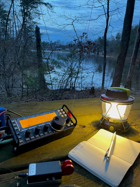
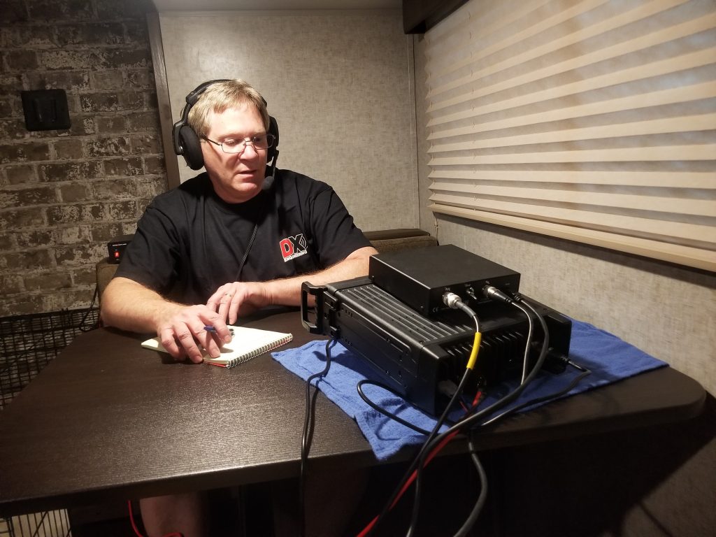
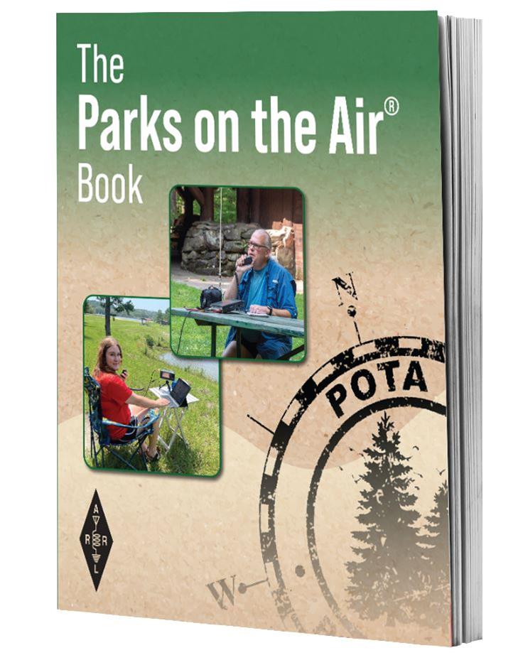
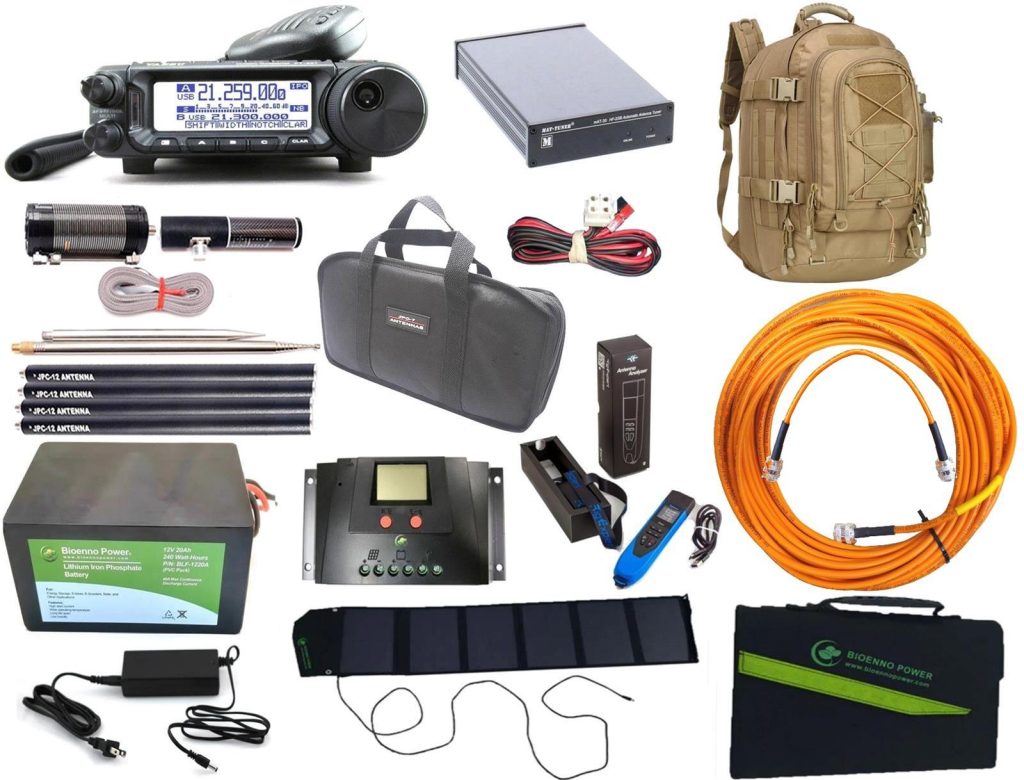
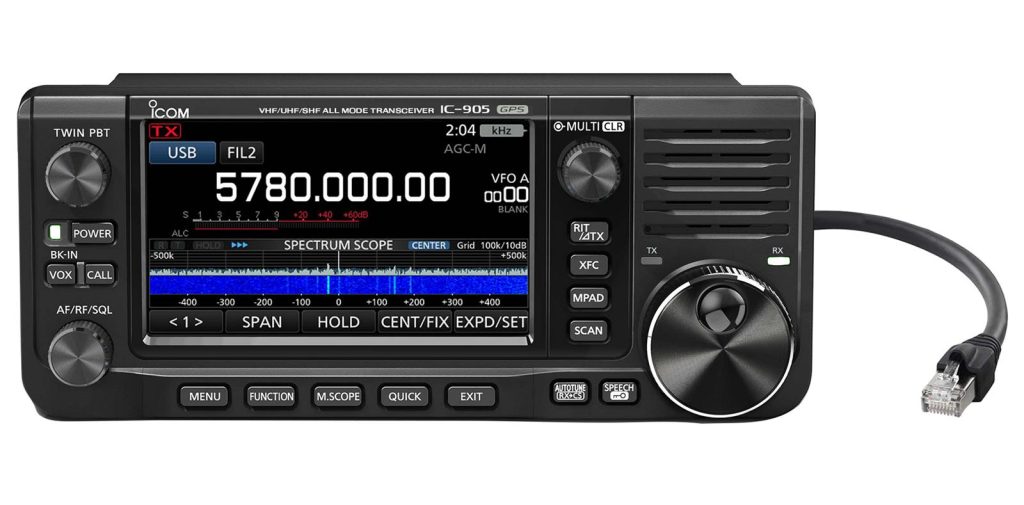
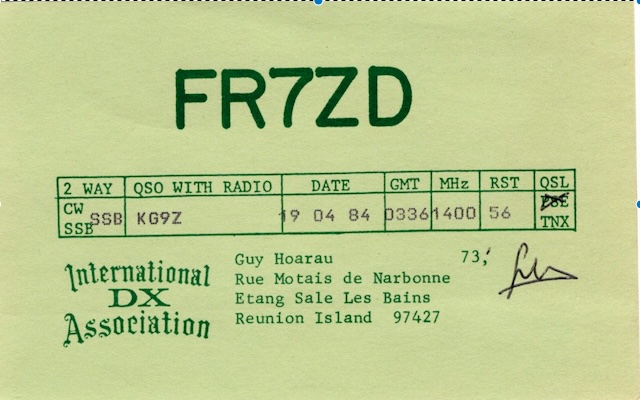
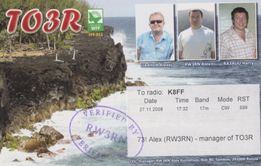
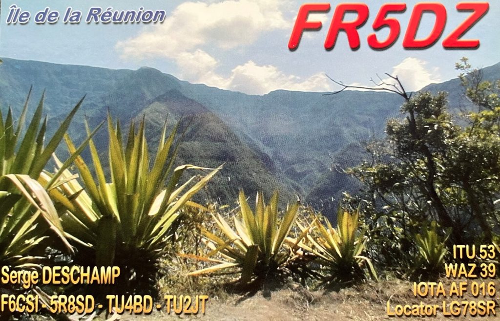


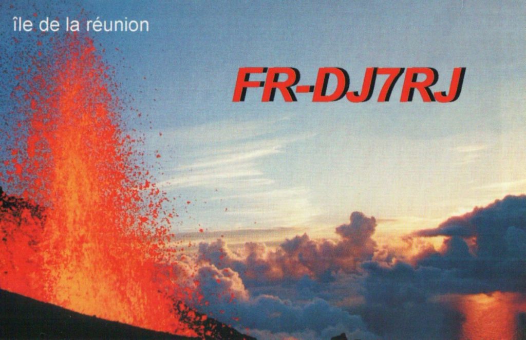
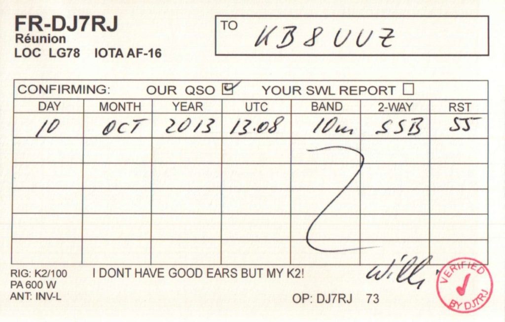
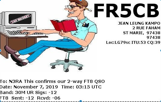
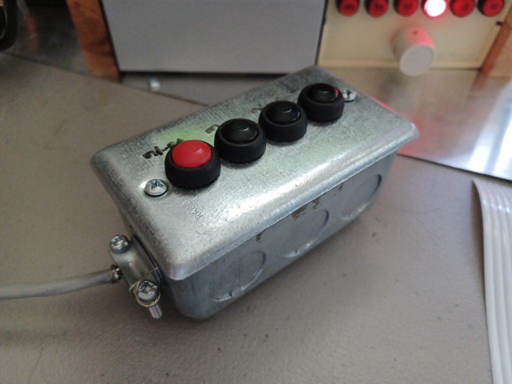
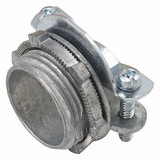
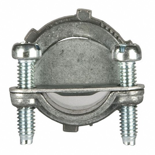
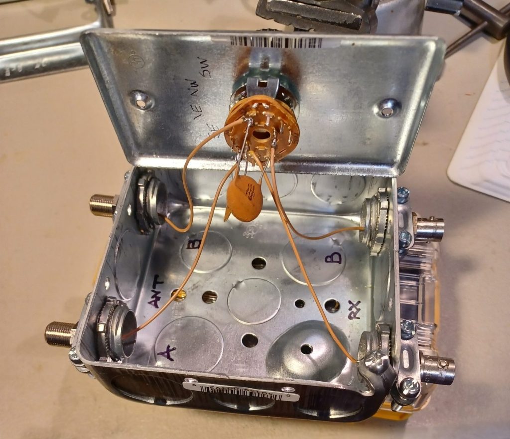
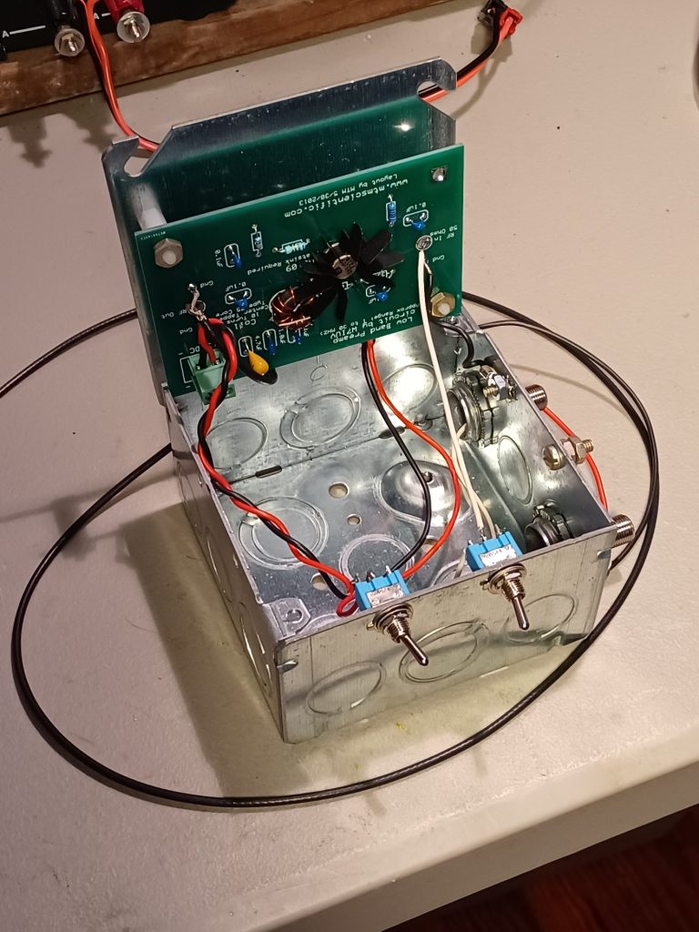
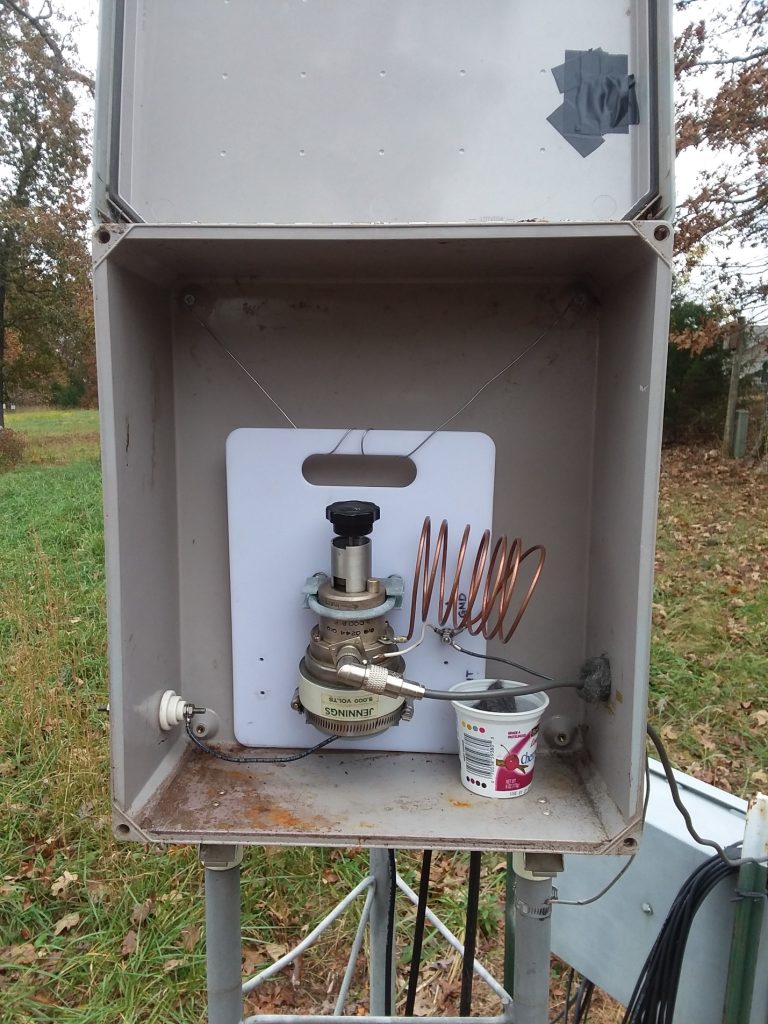
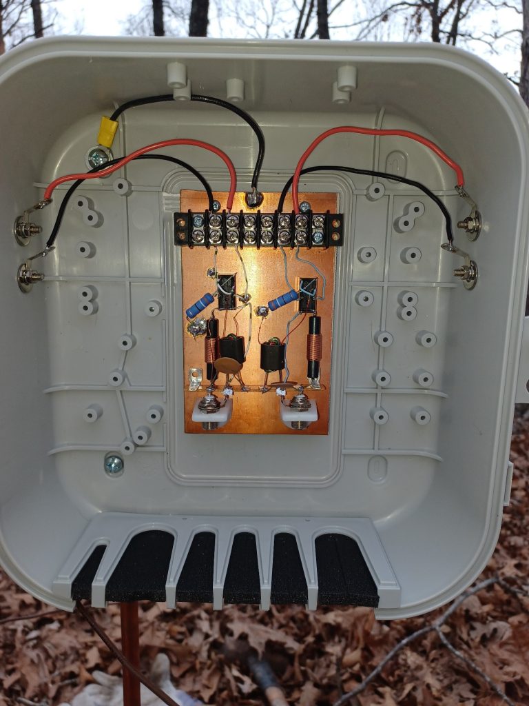
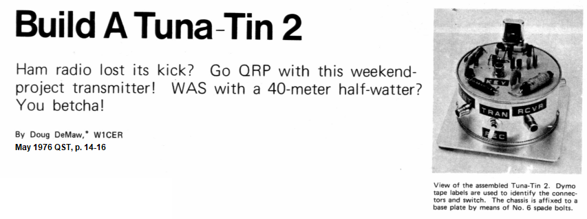
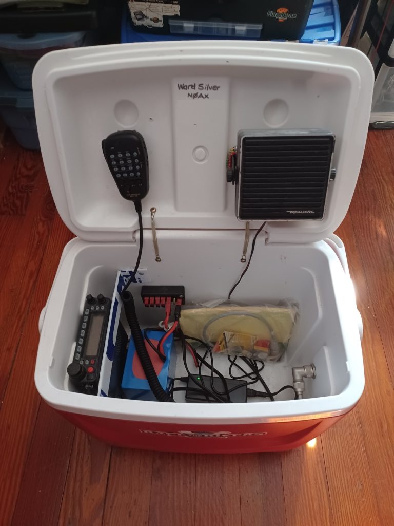
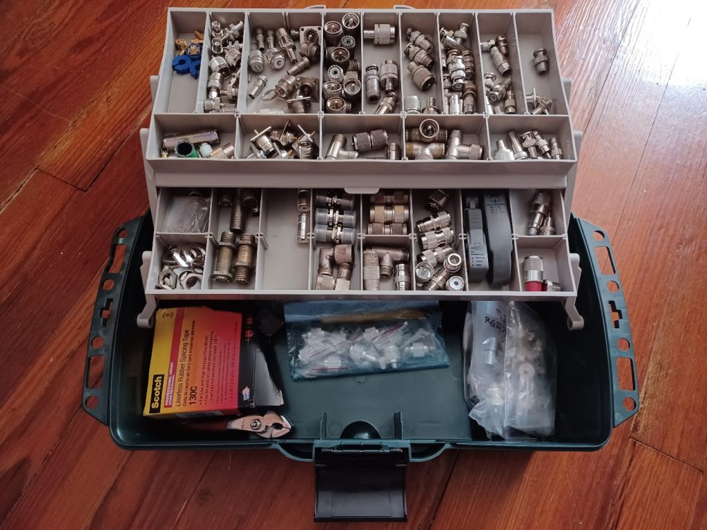
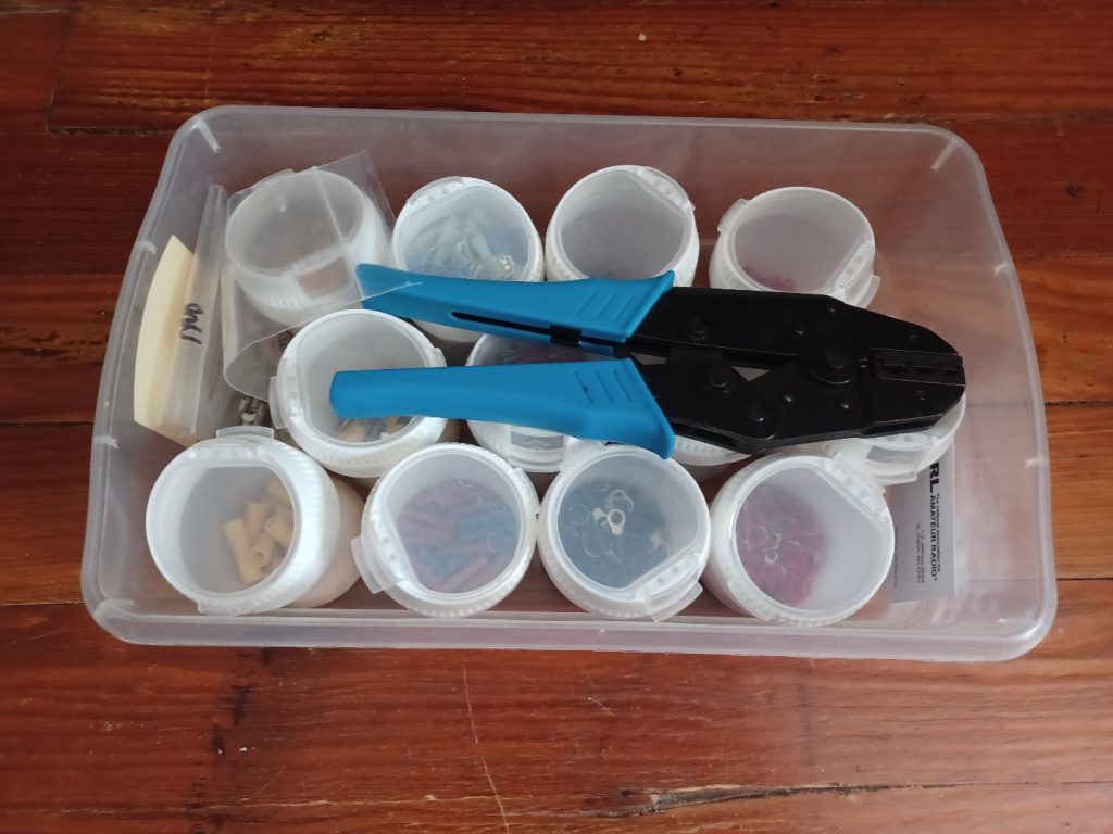
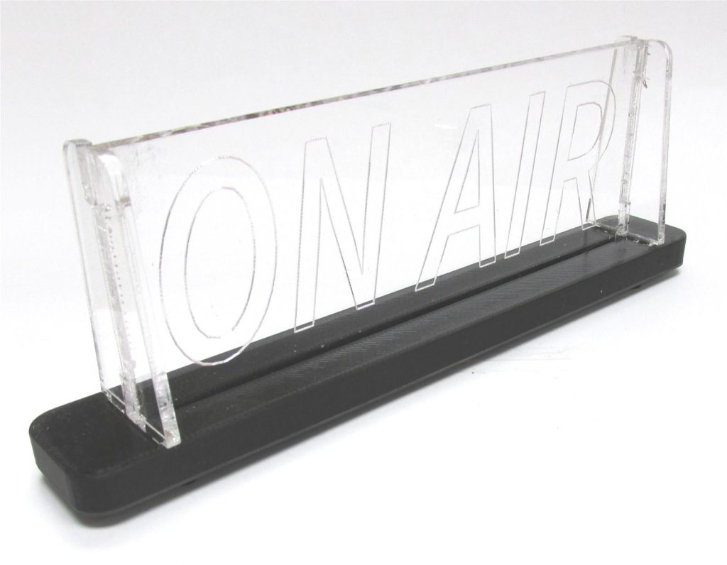
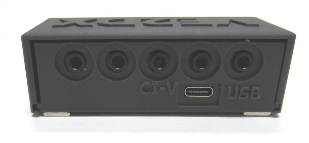
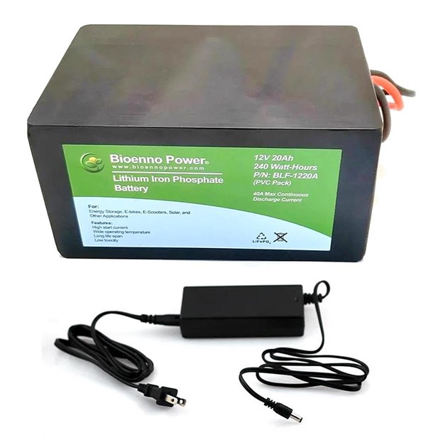
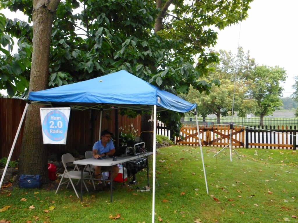
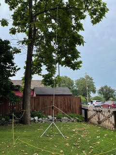
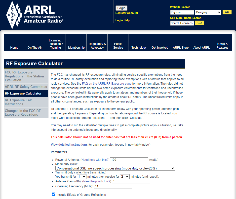
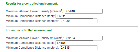
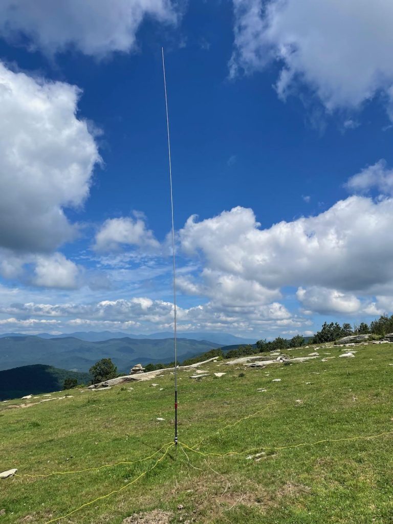
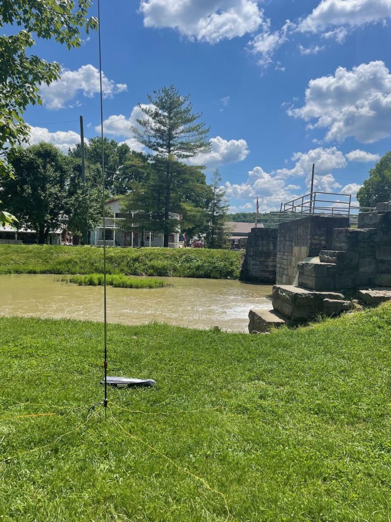
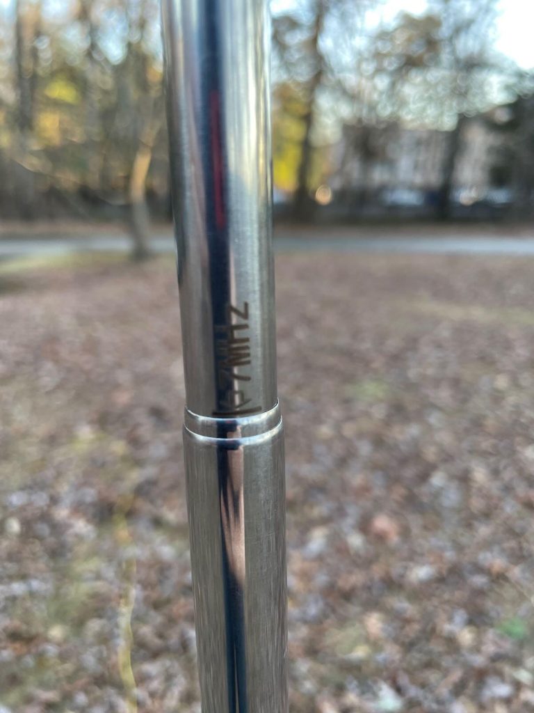
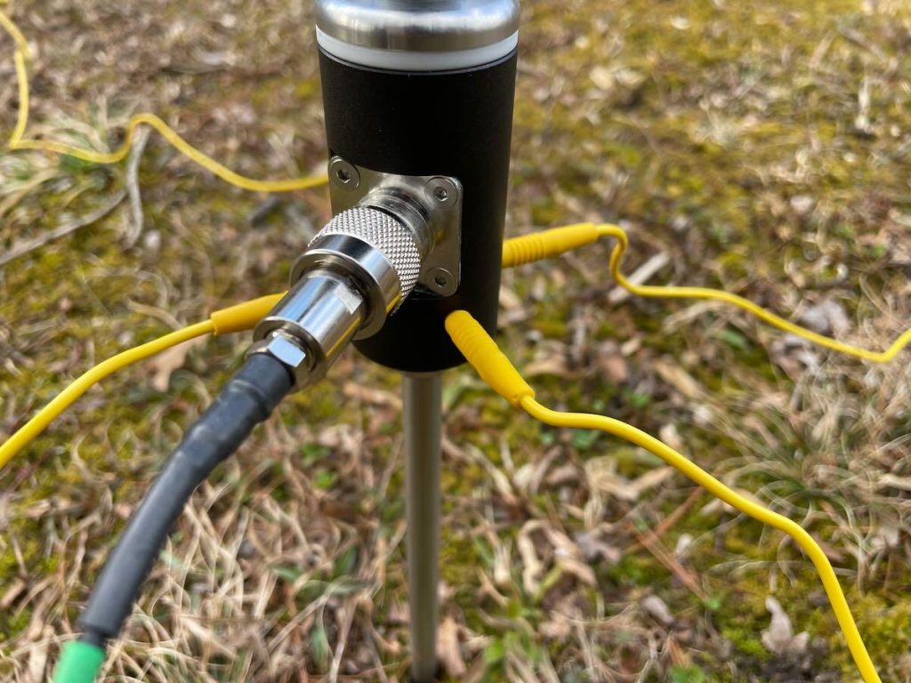
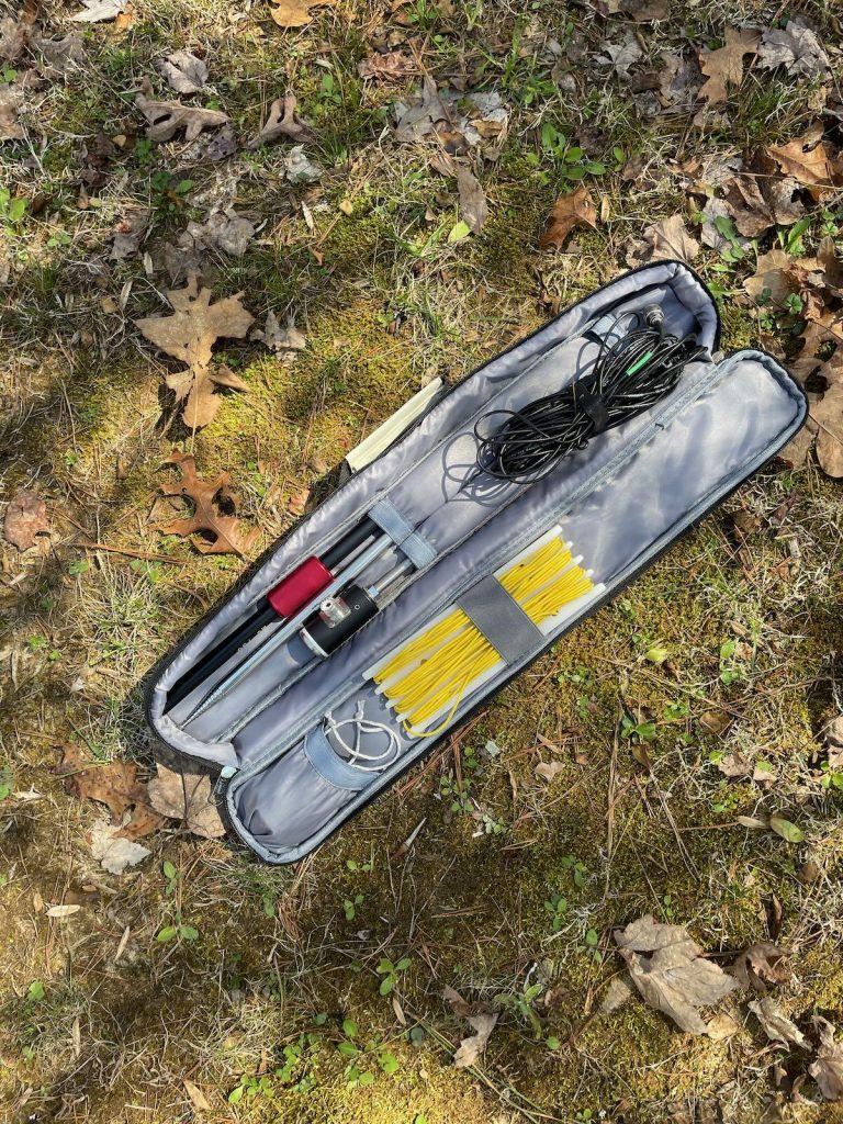
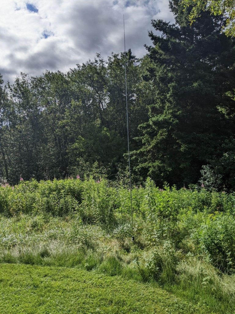
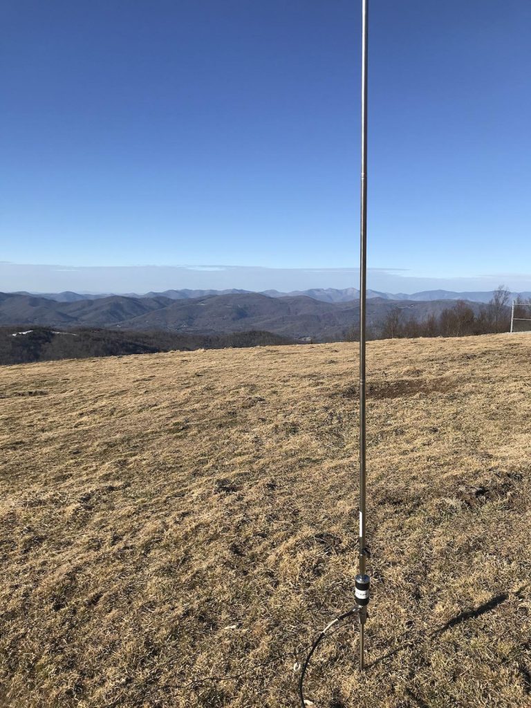
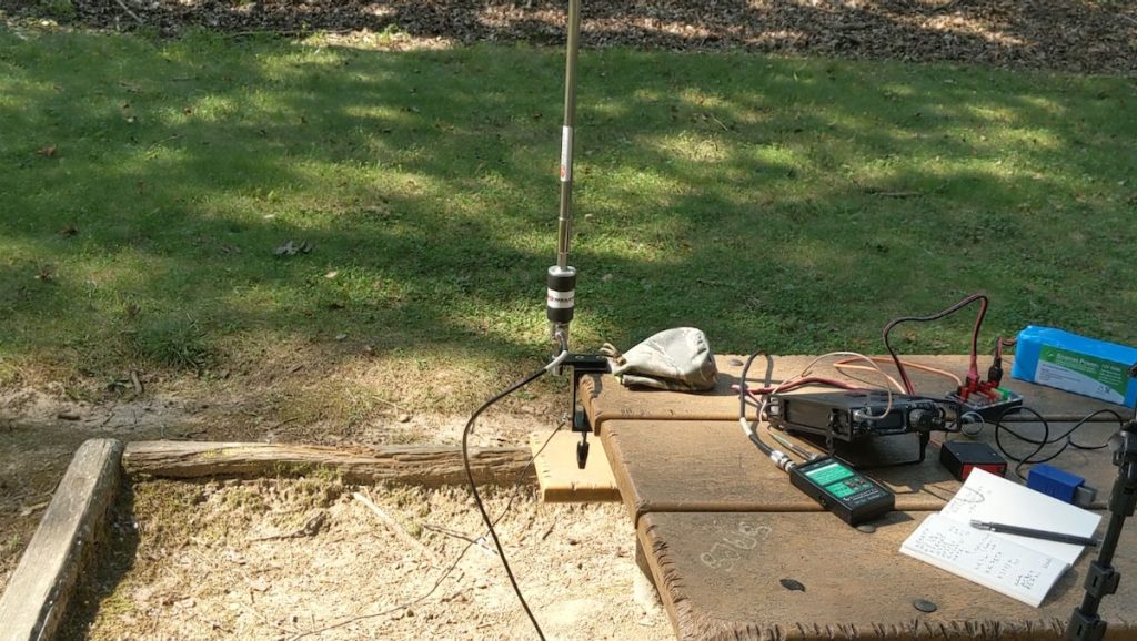
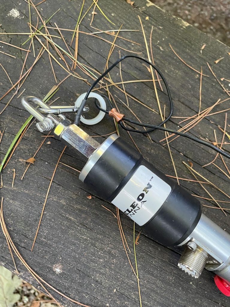
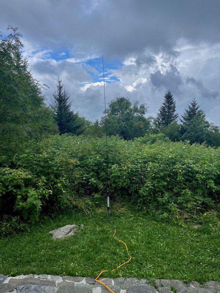
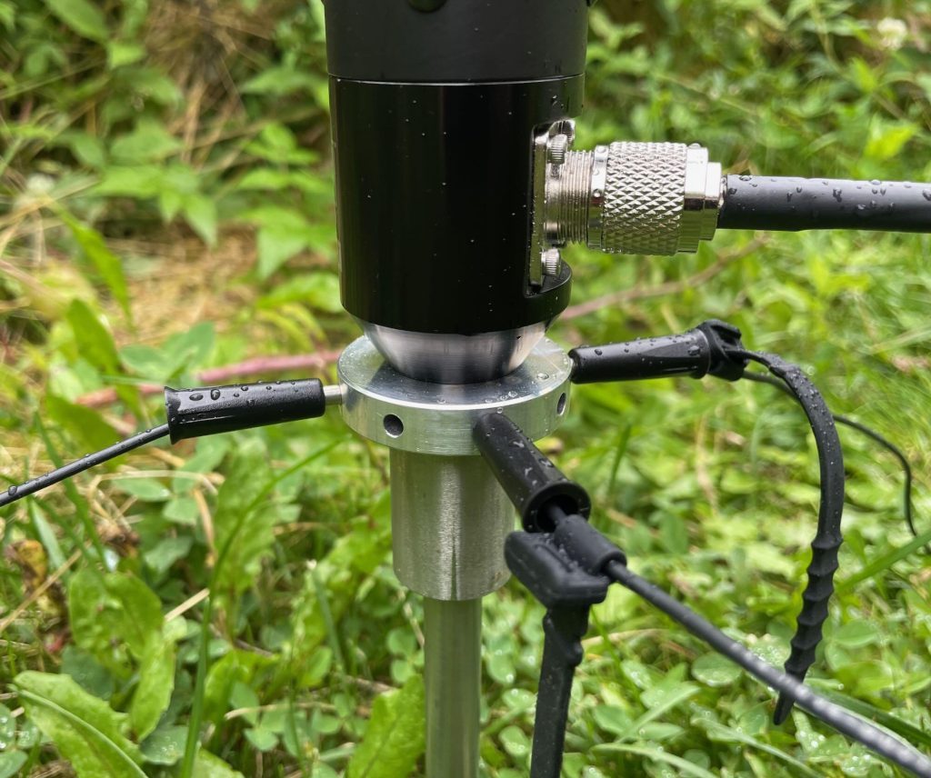
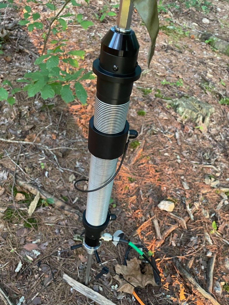
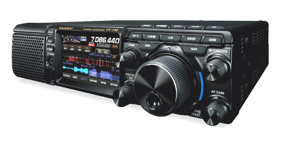
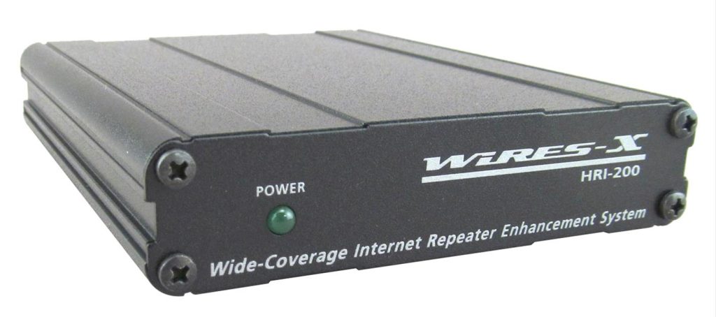

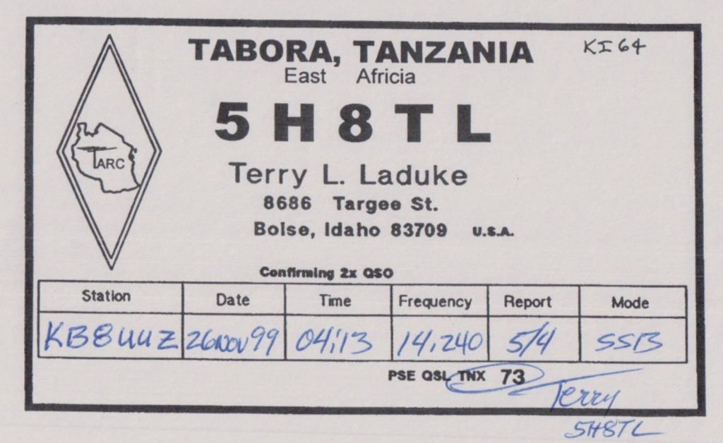
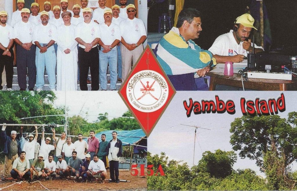
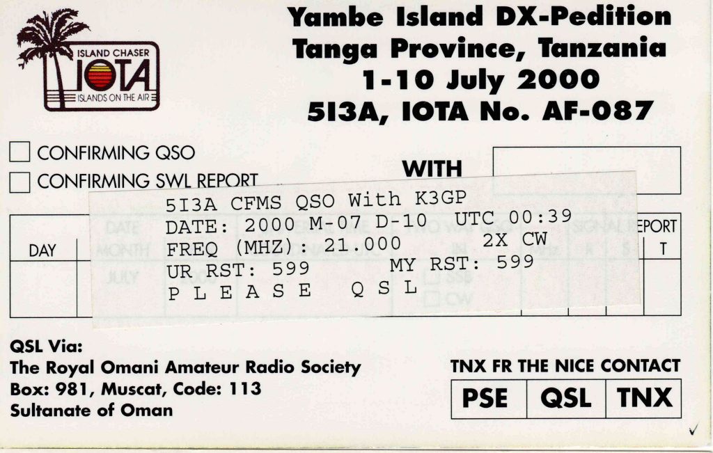

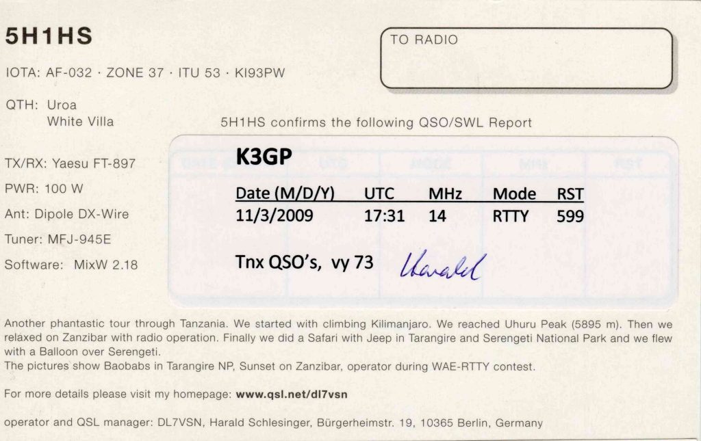
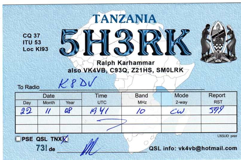

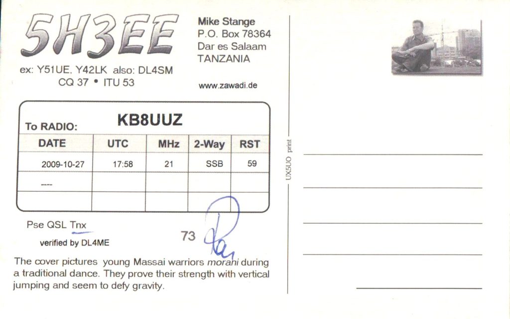
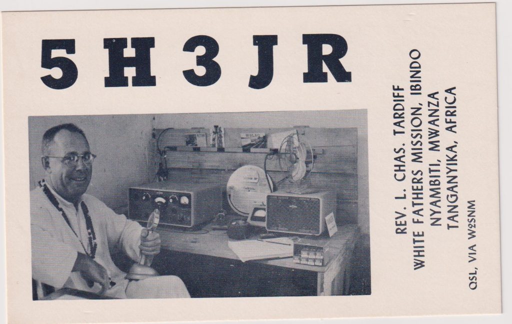
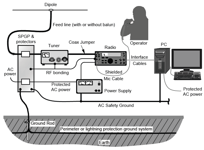
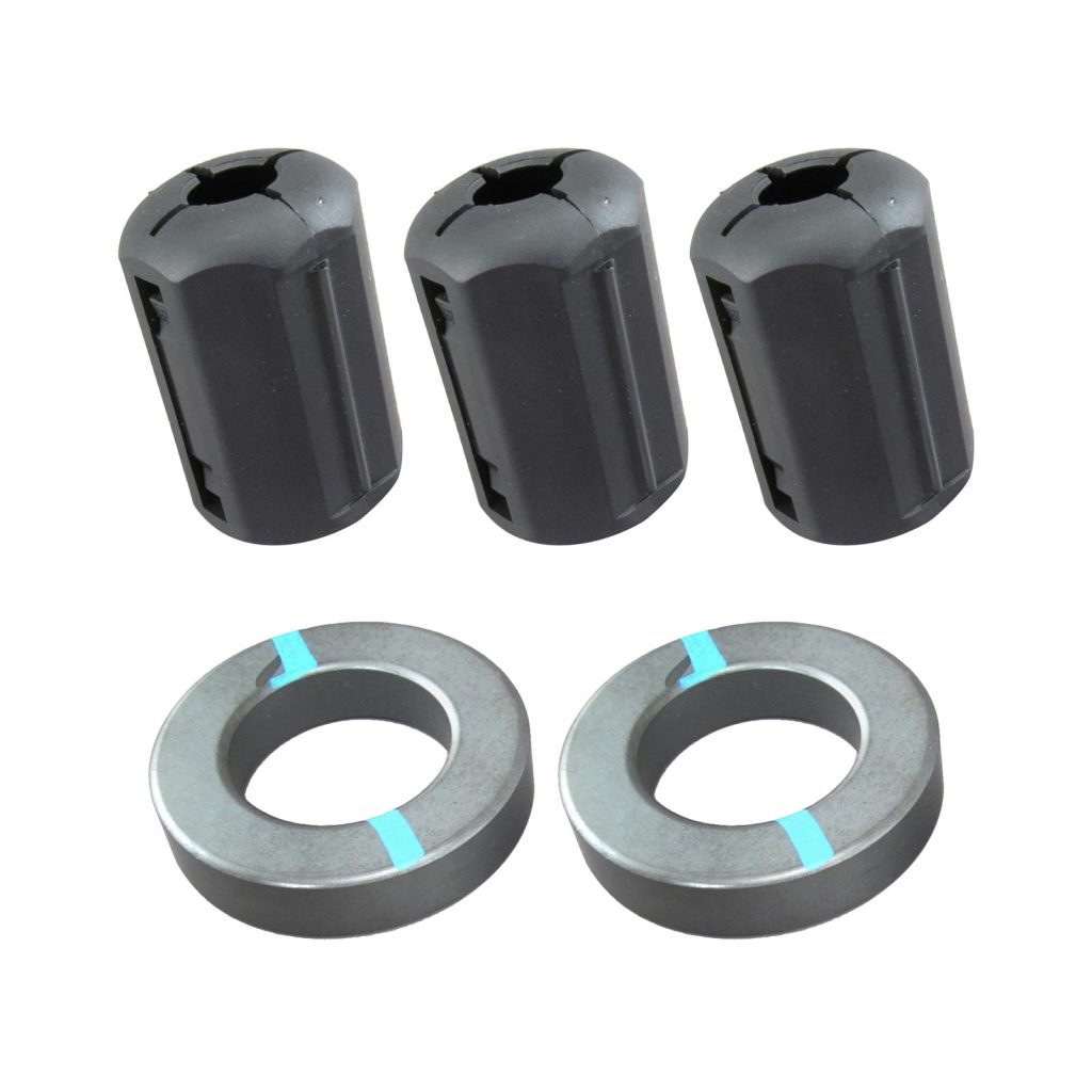
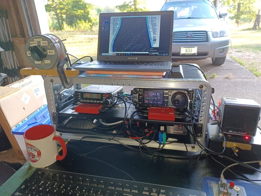
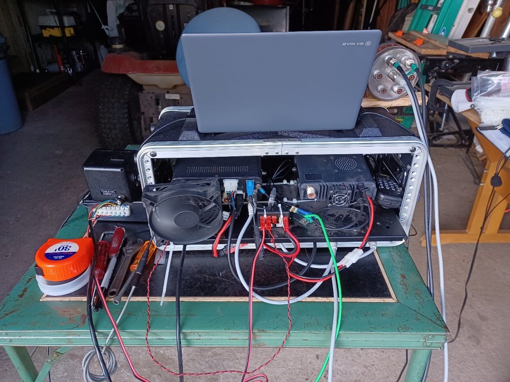
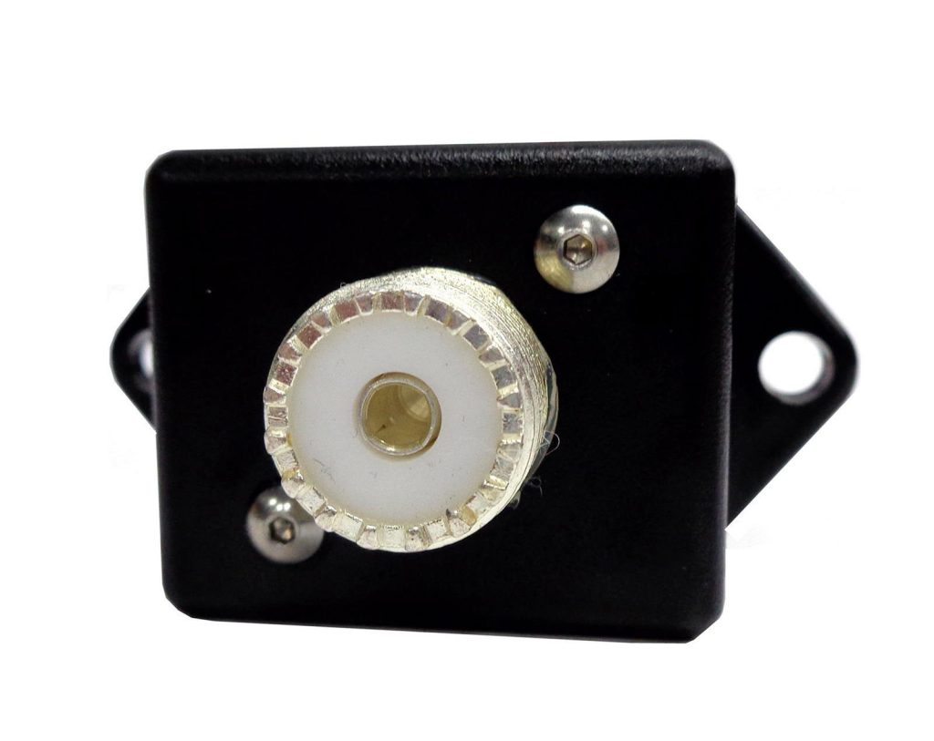
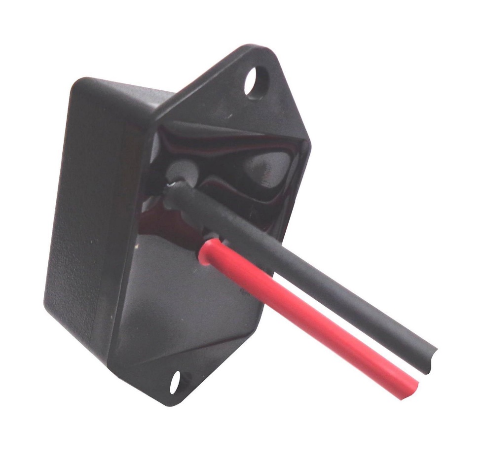
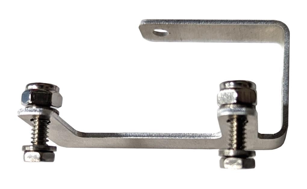

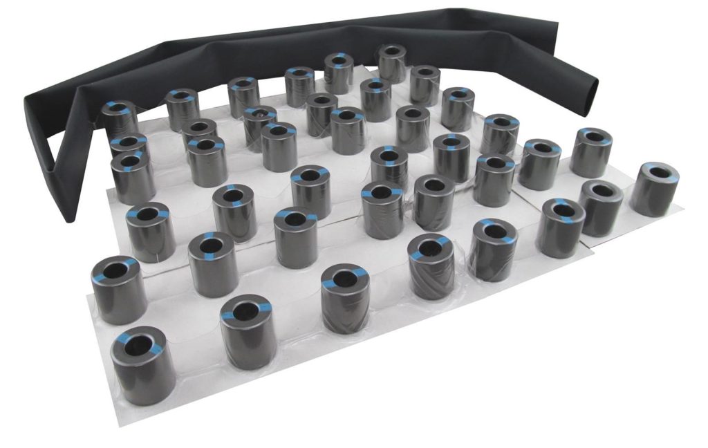
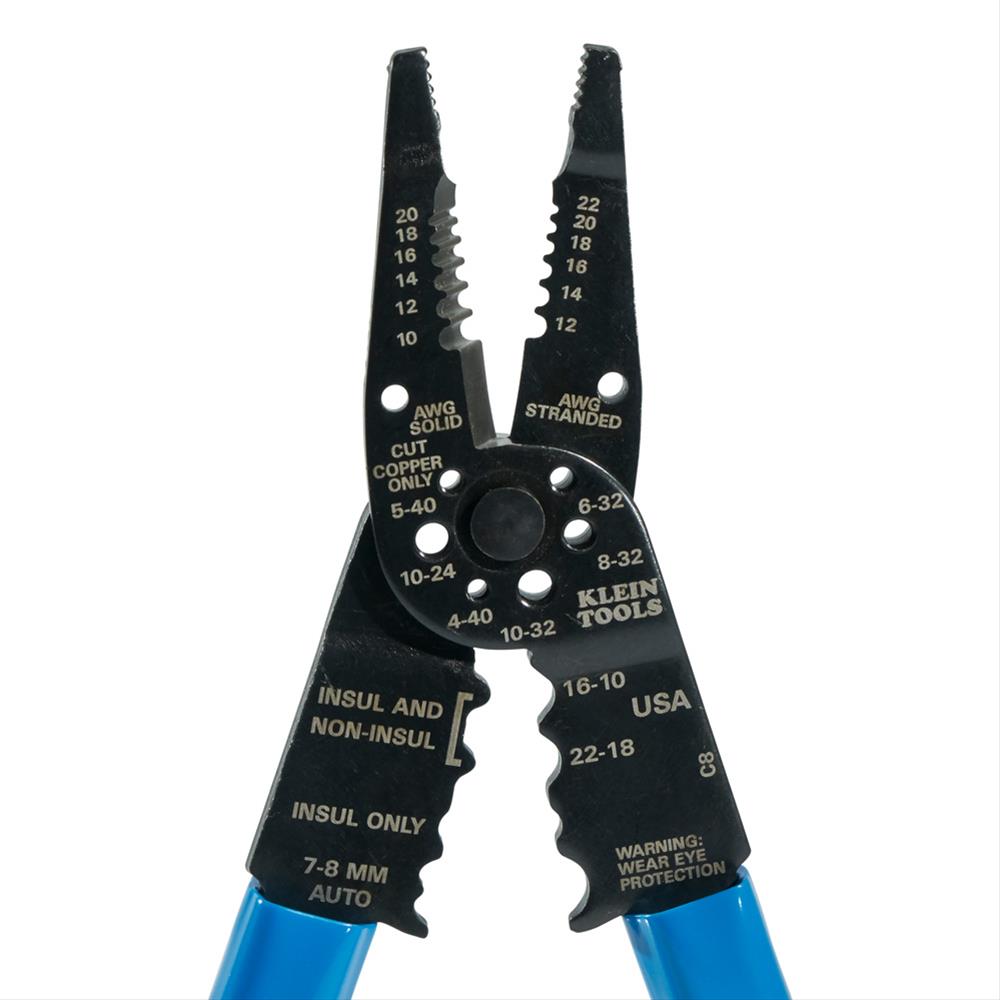
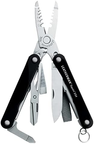
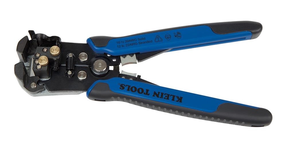
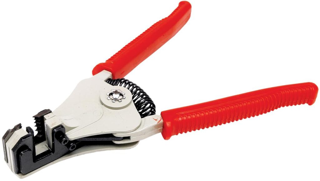
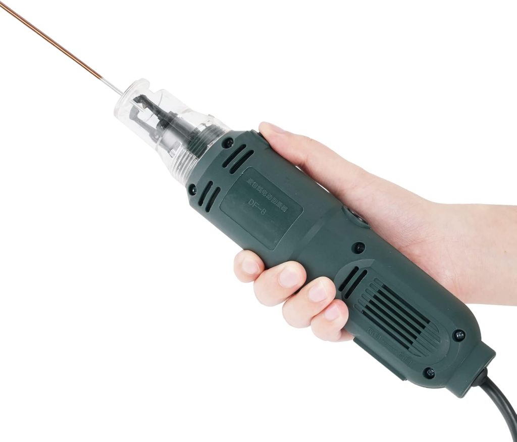
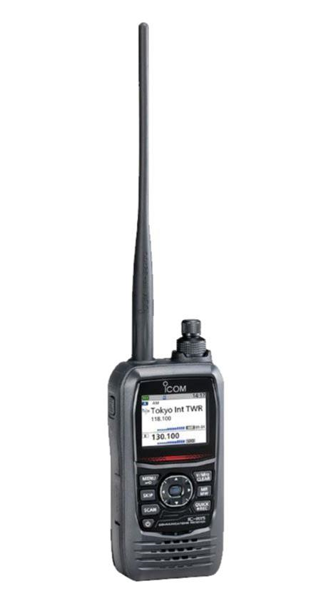
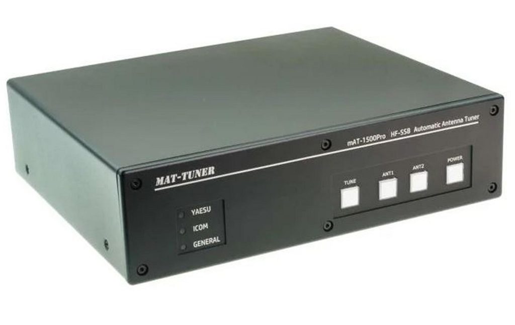
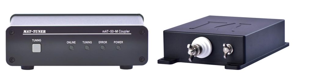
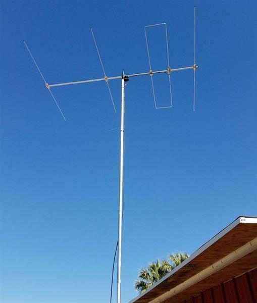
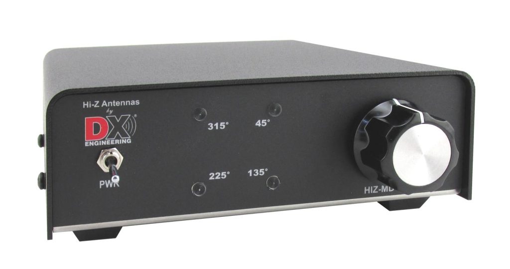
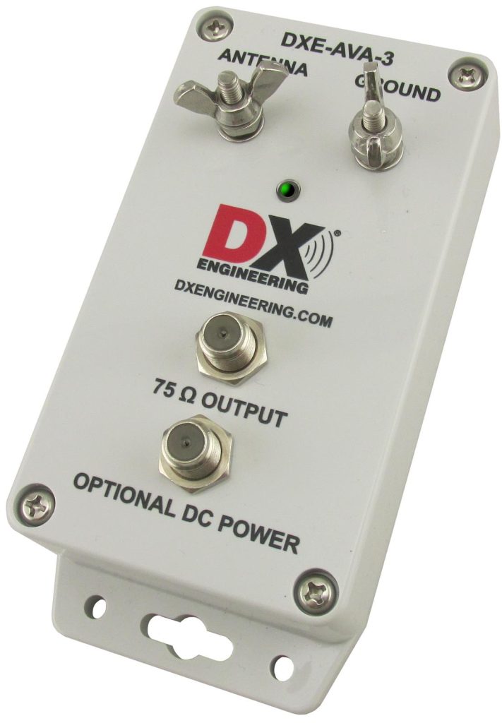
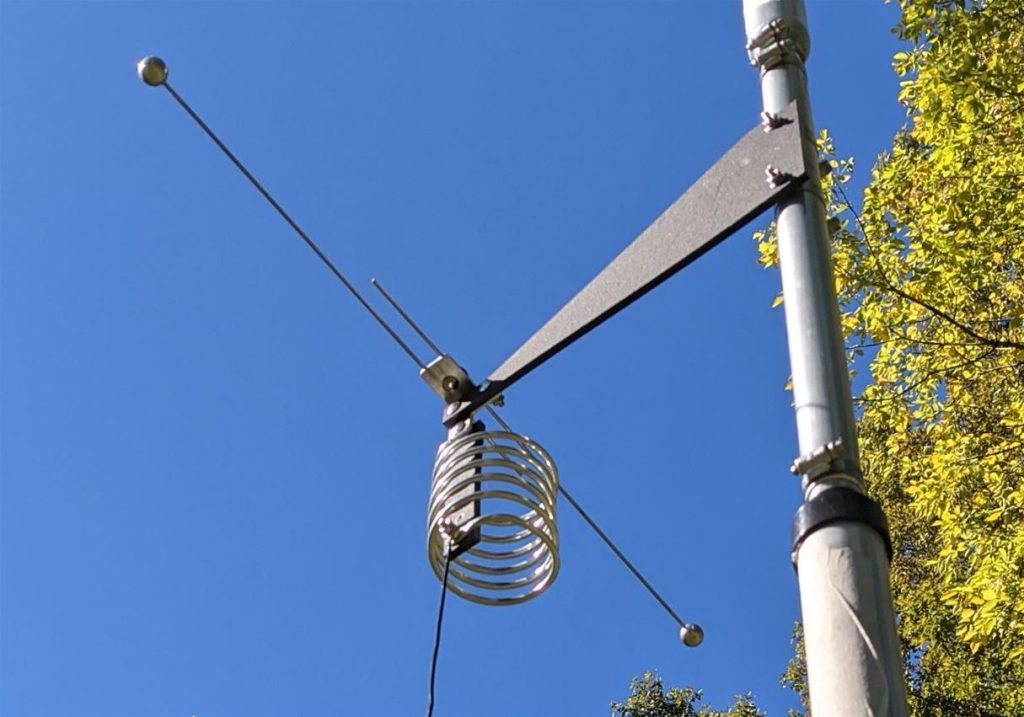
 Base, DX Engineering patented