
ELECRAFT KX3 & EMTECH ZM-2

Today's destination was a local highpoint close to my holiday home (static caravan) called Nicky Nook in the beautiful Forest Of Bowland. It's a lovely walk, with plenty of space to setup antennas with little risk of impacting other walkers. The climb is a surprisingly steep one, made all the worse by a set of high steps that sap your strength. There’s also some gravel paths inbetween. The elevation is about 750ft above sea level and it overlooks the Bay Of Morecambe, out to the Irish Sea and beyond.


It seemed like I had to pause for a break every few steps and I must admit that although I wanted to ‘soldier on’, it made sense to take my time and keep stopping to catch my breath. Crazy!
I was regretting leaving Betty behind - she would have provided some useful pulling power, LOL. Every time I saw someone coming down the track, I pretended to be taking in the views instead of looking like a frail old man with some sort of lung problems.
About 2/3rds of the way up, I spotted a little oasis. A small pond off to the right of the footpath, with some small tress which offered great shade from the increasingly hot sun. Normally I’d walk all the way up to the trig-point, but today wasn’t normal and I didn’t feel like going much further, so I hopped over the fence and sat under one of the trees.


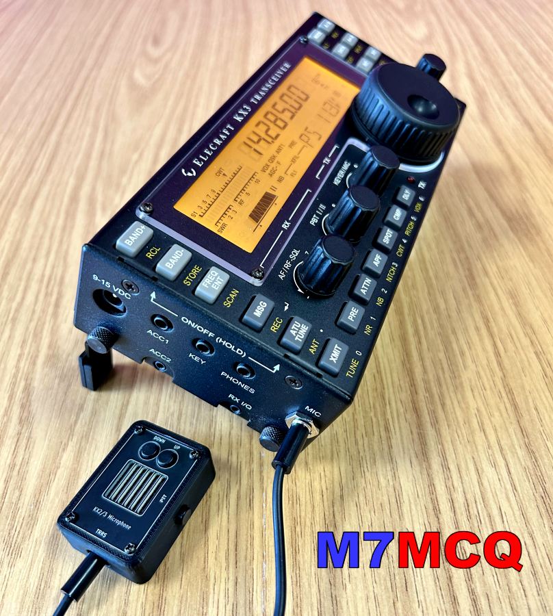
My KX3 doesn't have a built-in ATU - I use the amazing Elecraft T1 tuner which is a match made in Elecraft Heaven! The beauty of investing in a T1 instead of spending the same amount on an internal tuner, is that you can use the T1 with any of your qrp radios. It's a fabulous tuner with a very compact form factor - light and easy to operate. The unit runs off a PP3 9V battery and this will typically last for around a year before needing replacement.
However, when I was sorting out my gear to go on a radio-outing recently, I decided to leave the T1 behind and take my Emtech ZM-2. The ZM-2 is a fully manual tuner, requiring no power source which means that one needn't worry about the battery state or failure of relays, etc.
It's a 2-mile hike from the caravan to the peak of the hill, so I used my trusty RuckShack which (on this occasion) holds the following gear...
- KX3 Transceiver HF/4M
- HandHeld 2M Transceiver
- SotaBeams 20/40 Linked Dipole
- Sotabeams BandSpringer Multiband
- Hawkins Vipers 2/4/6M
- Emtech ZM-2 Tuner
- 13.2V LifePO Battery
- Headphones
- Bits & Bats!

Before long, I had my BandSpringer Midi erected which provides coverage on 8 bands, but requires the use of a tuner, so out came the ZM-2. The BandSpringer is a long wire with a counterpoise and is easy to erect using the telescopic mast.
Although I normally stick to my BandHopper when out and about, I really should use this BandSpringer more often! It gives you access to all those bands which makes it far more versatile than the dipole and gives you more chance of bagging contacts.
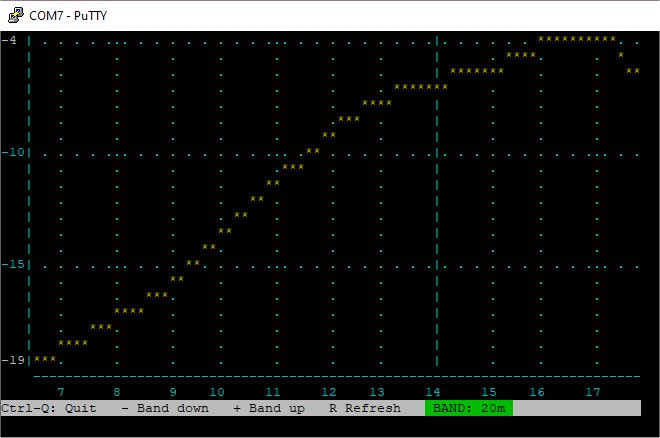
The first band to be worked was trusty old 20M and it was surprisingly quiet!! I found a few very strong European stations who were using mega-power, but I couldn’t hear who they were talking to and I couldn’t get through to most of them either.
VIDEO OF THE LOCATION
I started to use the KX3's memory keyer to call CQ on 14.285MHz until I got a response. It took an awful long time before I had my first QSO. I tried the other bands but only had any luck on 17M with a contact from UA3QKA in Russia. Following that, I switched to 40M and conditions weren’t much better to be honest. I managed to speak with DL8ECA/P and no one else. I moved to the QRP frequency 7.090MHz to call CQ, but unfortunately (as is often the case) there were a couple of QROOOO Italians chin-wagging, making it unusable - even a few k either side!
I'm fully aware that 14.285 and 7.090 are designated as the "Centre of QRP Activity" and not owned by QRP operators - yes - anyone can operate there. But surely it's just common decency (not to mention good practise) to avoid these frequencies when you know that people using low power look to that part of the band to stand a chance to be heard - especially when others are chucking out 1000W! 😲 It's a similar situation on FT8 frequencies, where you can frequently hear Italian accents blasting over .074MHz. Surely to god they must know how their massive signals are impacting adjacent frequencies? Or maybe that's what FT8 haters do??
Anyway, I'm digressing. Back to my lovely day spent outdoors.


After giving up on HF, I was keen to see if I could catch anyone on 70MHz, so I erected the 4M Hawkins Viper and gave it a go. Now bear in mind that the KX3 only puts out about 3W on 4M, but I figured that my location might provide some much needed 'gain'.
I started with some AM shouts on 70.260 and got no response, so I moved up to 70.450 FM. Sadly, no one was around, so before giving up I tried some SSB down at 70.200 - nothing.
Ah well, the day wasn’t wasted - I was sat in a glorious spot with the sun shining, fabulous views and beautiful bird song. This day was also the day (26yrs ago), that my wonderful son Michael died, so it was nice to sit in this peaceful spot and remember how lucky we are to just enjoy these simple pleasures and to remember to make the most of every beautiful day we have.


Tom, M7MCQ.


