 (the frame is actually dead straight, the distortion comes from the camera)
This article is about the implementation of the idea of building a (decorative) QRP radio for digi mode operation that can be operated remotely via Wi-Fi. One possible use would be to place the device together with a simple vertical antenna and a small battery, e.g. temporarily in the garden, so that it can then be operated from the computer from inside the house. The basic idea is to be able to conveniently control the device remotely via VNC.
I had set myself the following conditions:
- The transceiver should be inexpensive and easy to set up
- The setup should include an automatic antenna tuner that does not require any manual interaction
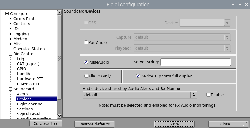
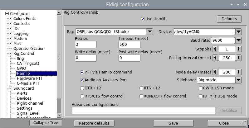
- A Wi-Fi-capable single-board computer should be integrated, on which the required software (WSJT-X, JS8Call, Fldigi) can be executed
- The entire system should be able to be operated with 13.8V and only require one power supply line
- The costs should not exceed 250€, ideally around 200€
- It should be cool looking / decorative (from a techie’s perspective)
I then decided in favor of the following components
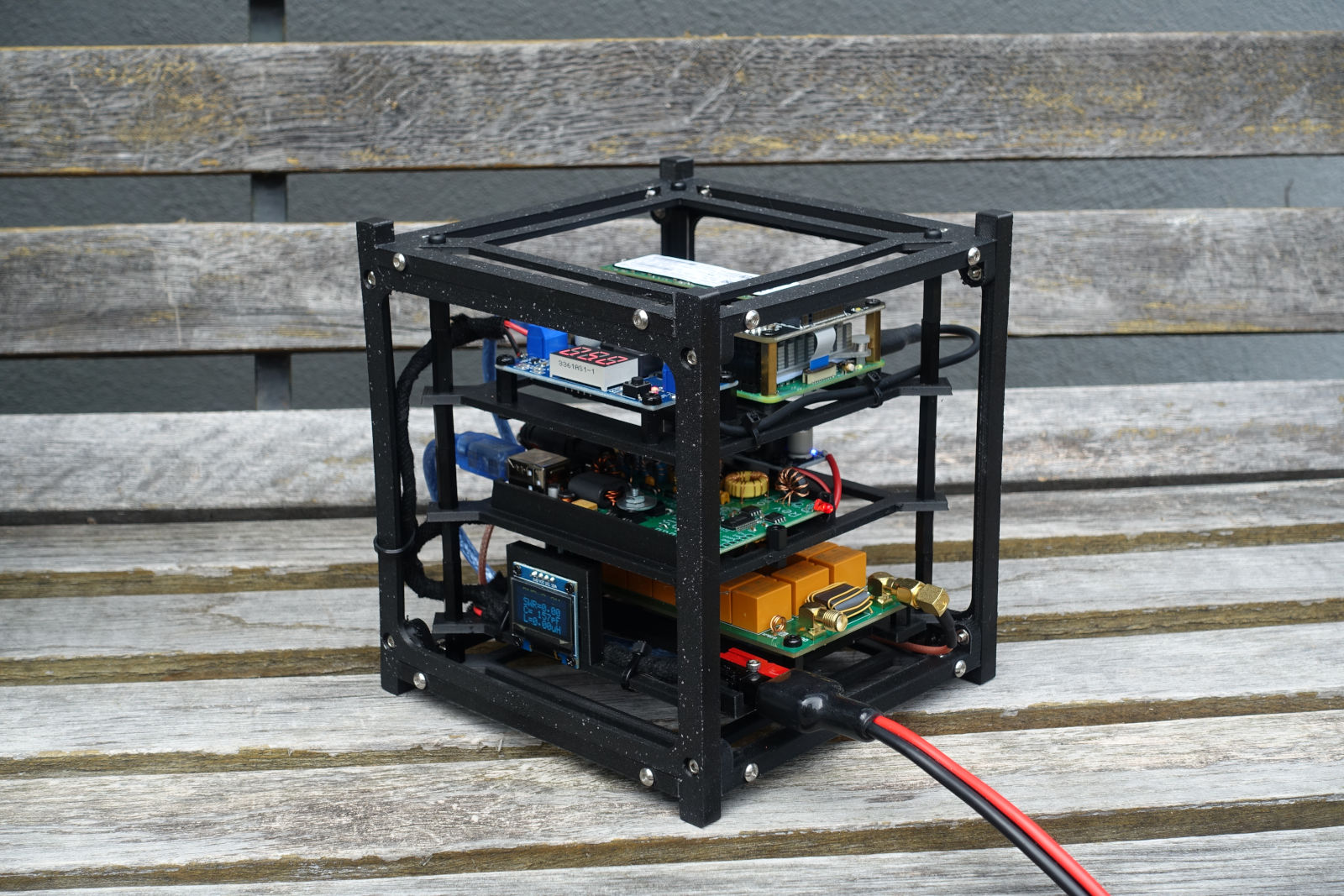
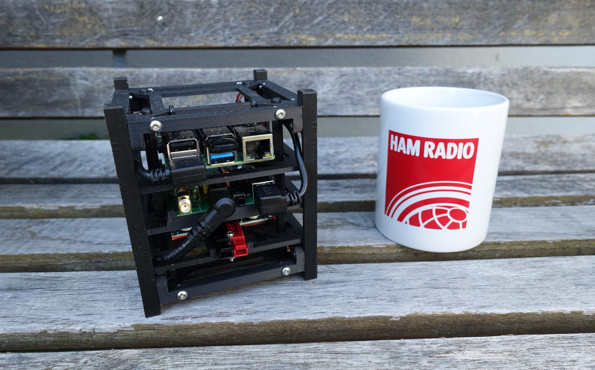
Before the implementation began, I first had to come up with an idea for a suitable enclosure. After seeing a CubeSat at Hamradio 2024 in Friedrichshafen, I had the idea of making the entire setup look like a CubeSat and building it on a modular, skeleton-like structure. I finally found inspiration in the following design on Thingiverse: https://www.thingiverse.com/thing:4096437
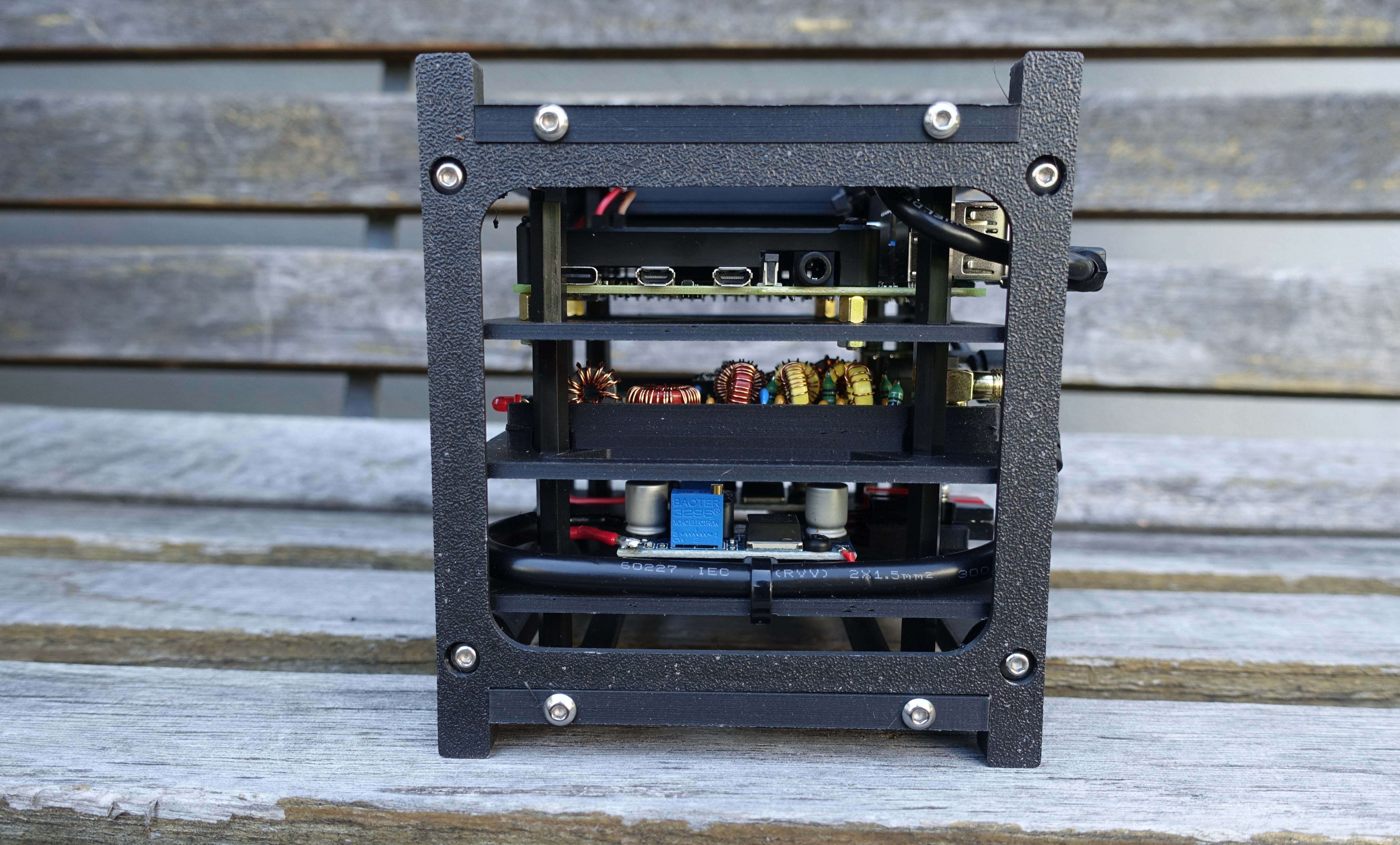
Unfortunately, I had to realize that a 10x10x10cm cube didn’t offer enough space for my project, so I created a 14x14x14cm version based on the previously linked project. I enlarged the side panel and the base plate accordingly and designed 3 new modules for the following components (from bottom to top):
- ATU, OLED display and Powerpole connector
- QDX transceiver and buck converter (7V, please see my notes on the QDX)
- Raspberry Pi 5 and buck converter (5V)
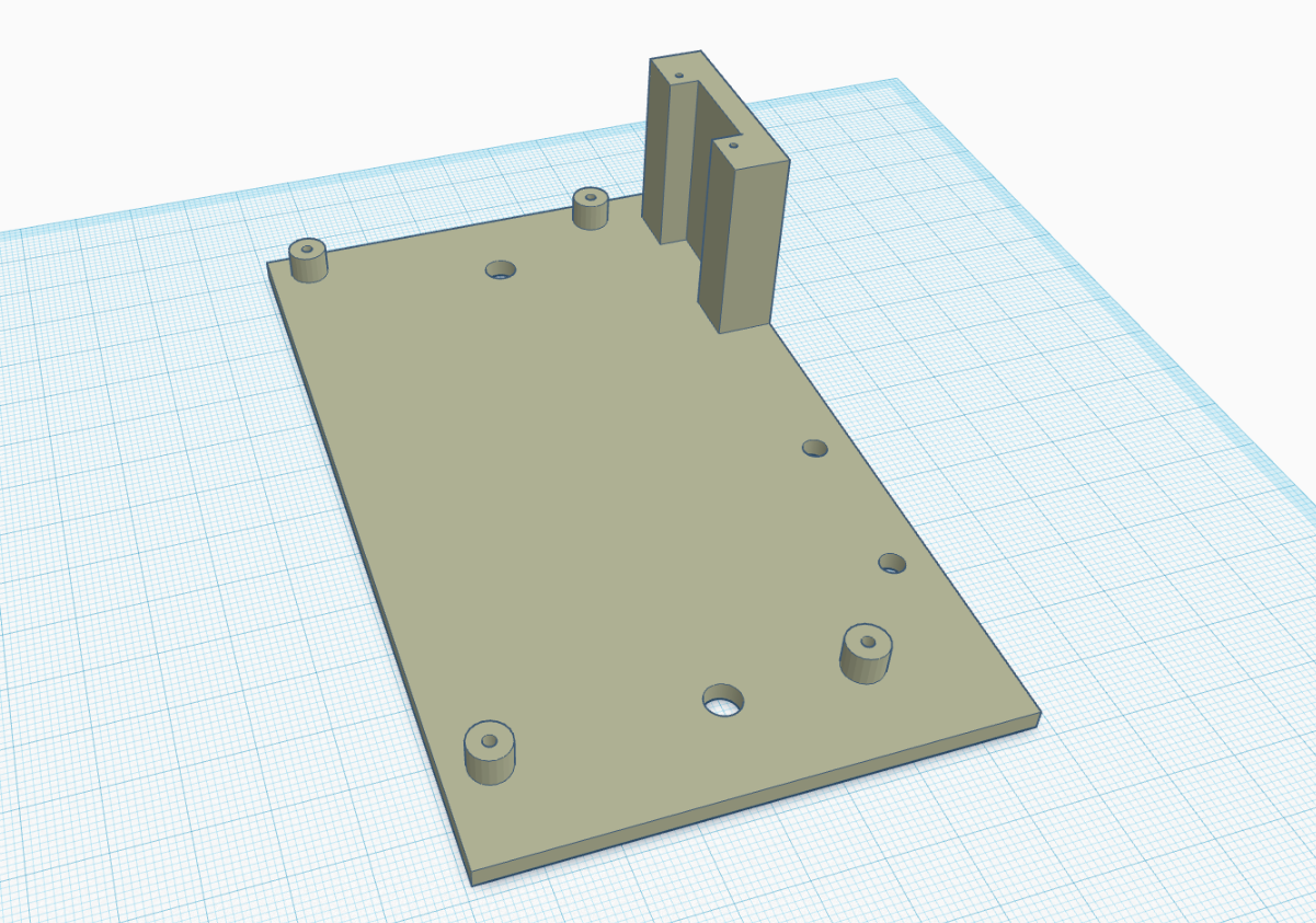
All 3D printable parts used in this project can be found on Printables.
First of all, the individual components had to be assembled:
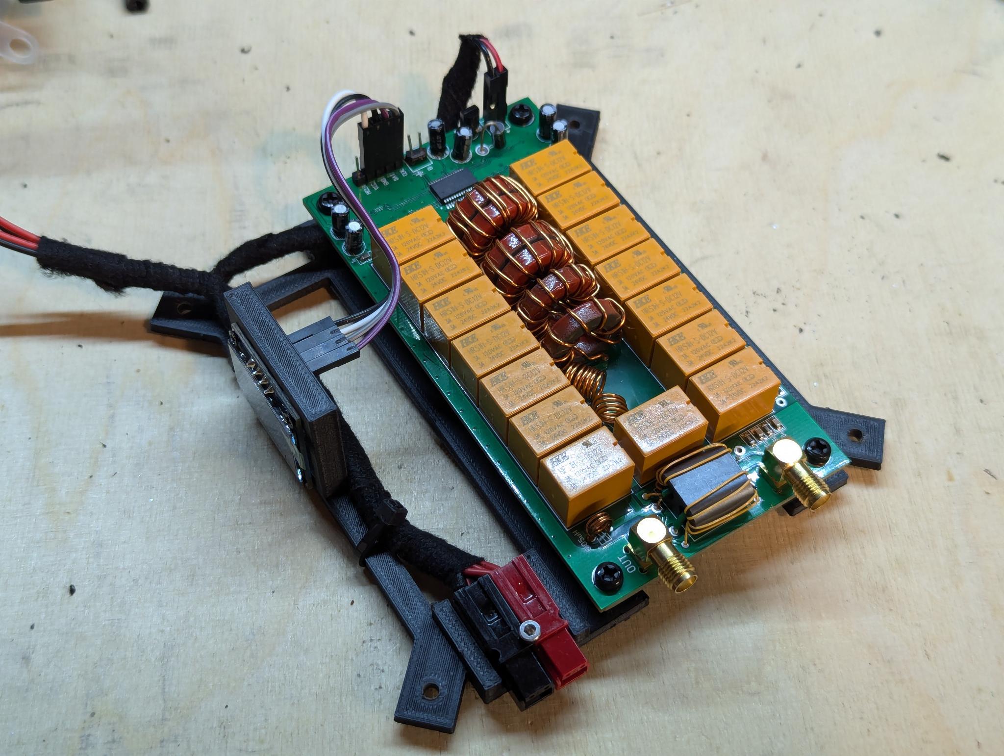
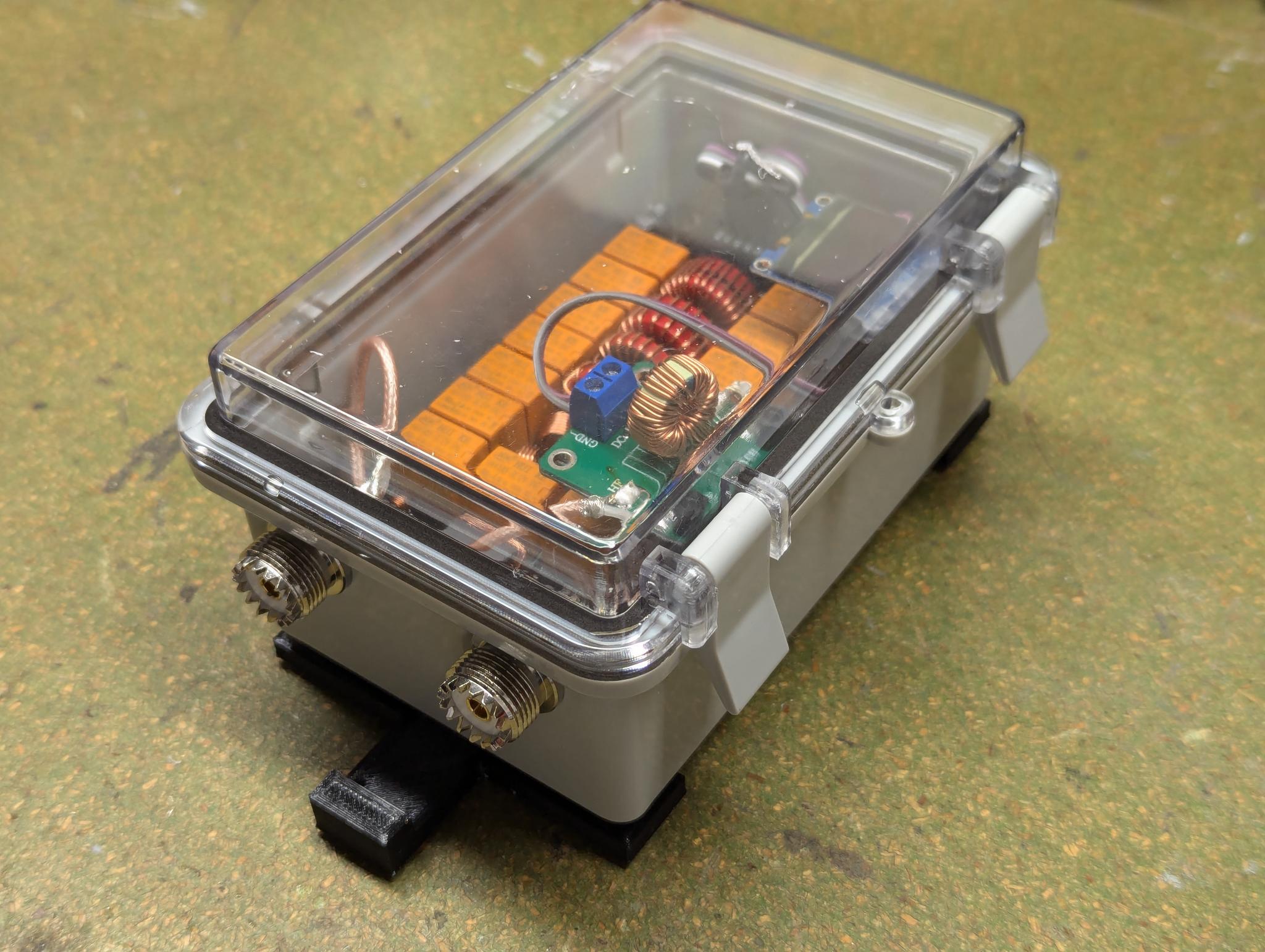
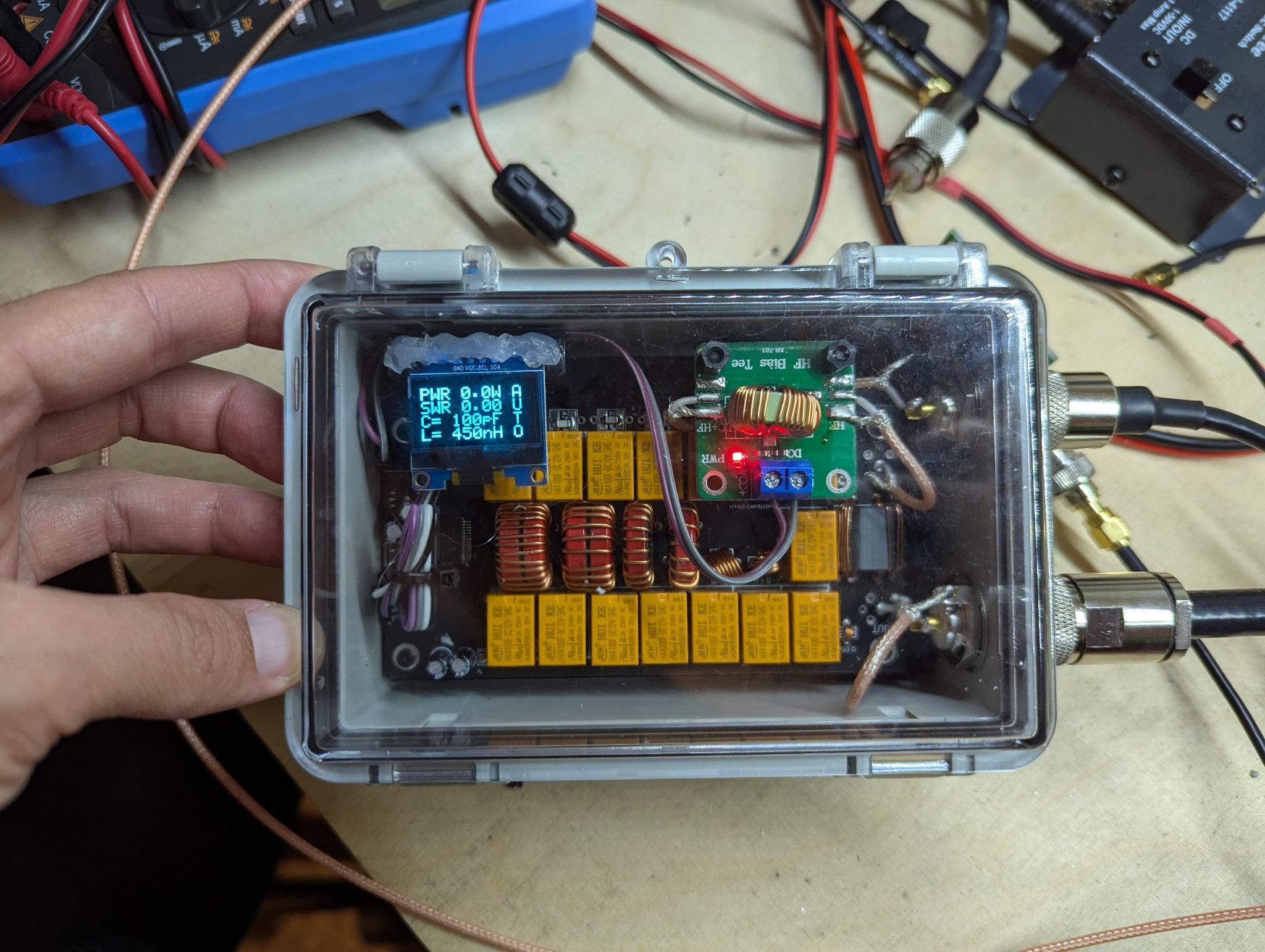
Antenna Tuner Module
The kit for an ATU-100 to N7DDC can now be obtained for just 35€ including shipping. Apart from the binocular transformer, I built it according to the instructions. The transformer only needs 5 instead of 10 windings on both sides to be able to use it for QRP operation. After the kit was finished, I downloaded the original firmware and flashed it to the micro controller with a PICKit3 programmer. I made the following two modifications:
- QRP operation by setting cell 05 to the value 01
- Fully automatic tuning based on the measured SWR by setting cell 02 to the value 01
You can find more details in the ATU-100 manual on Github
For more information on the QDX in combination with an ATU, please see my notes on the QDX.
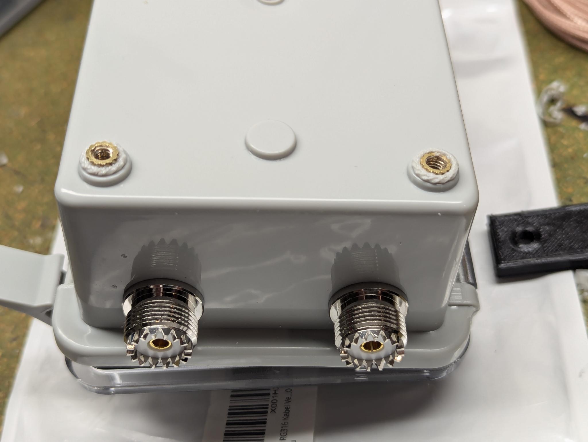
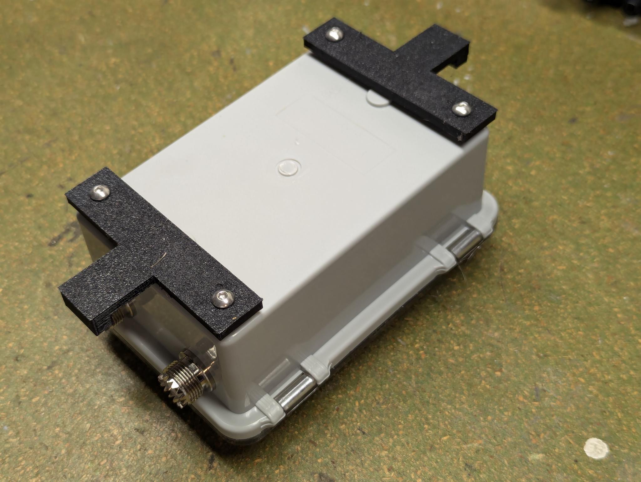
The tuner was then installed together with the display and a Powerpole connector on the specially designed and printed module carrier:
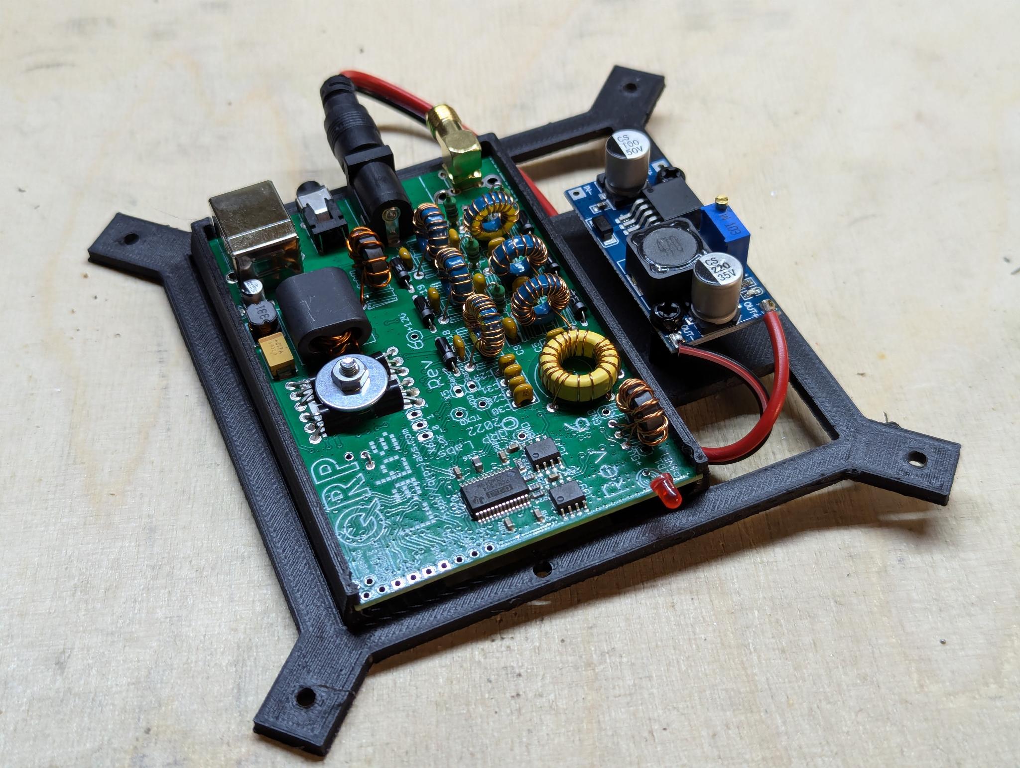
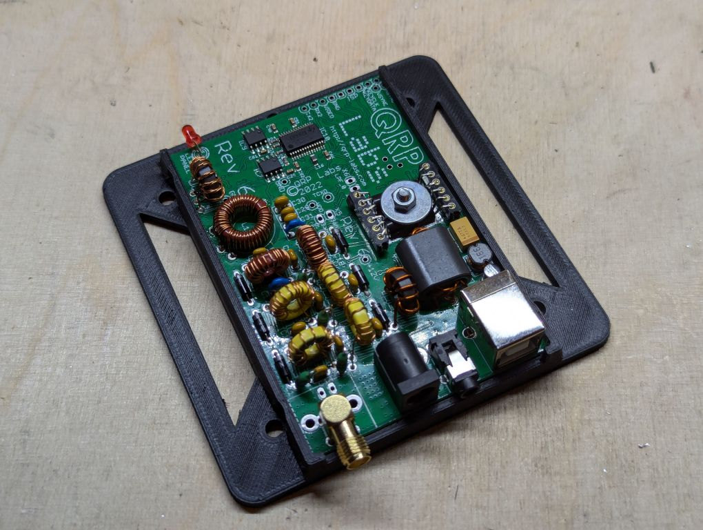
Transceiver Module
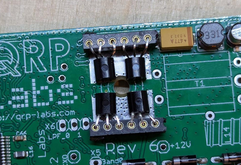
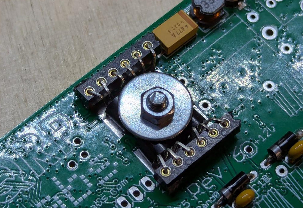
Now it was time to set up the QDX transceiver. The unprecedentedly good assembly instructions from QRPLabs left no questions unanswered, which is why the assembly turned out to be quite simple.
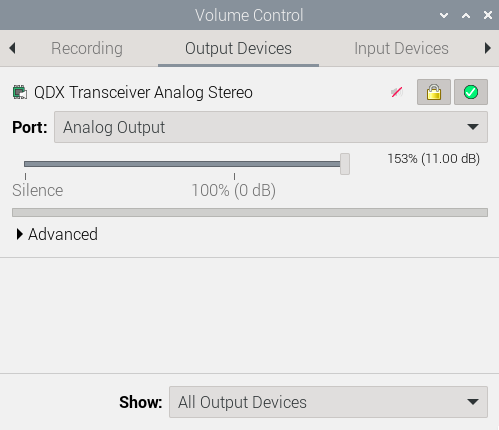
The finished QDX was then inserted into its module carrier. In addition to the QDX, a buck converter was installed on the carrier, which regulates the 13.8V for the QDX down to 9V.
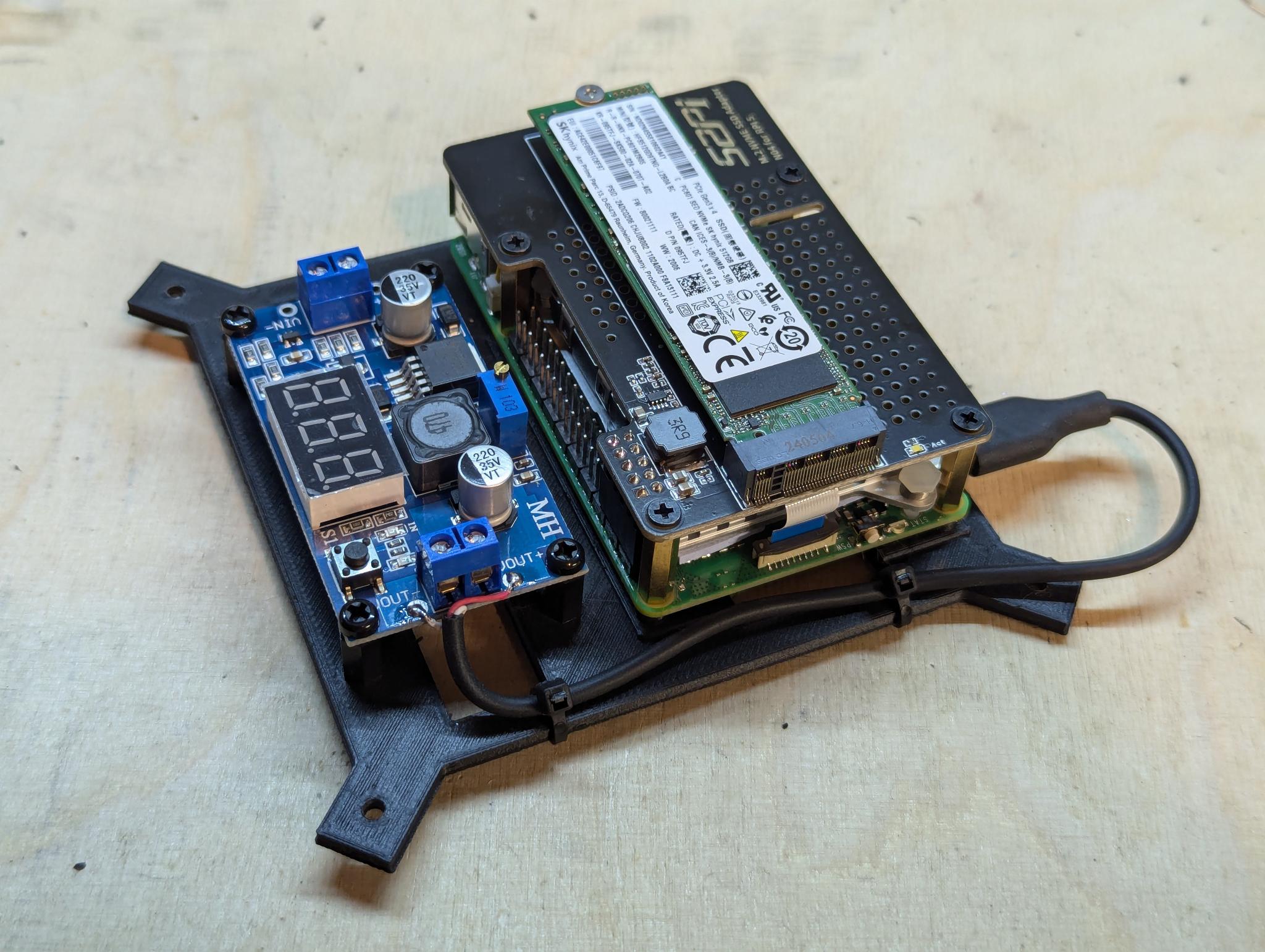
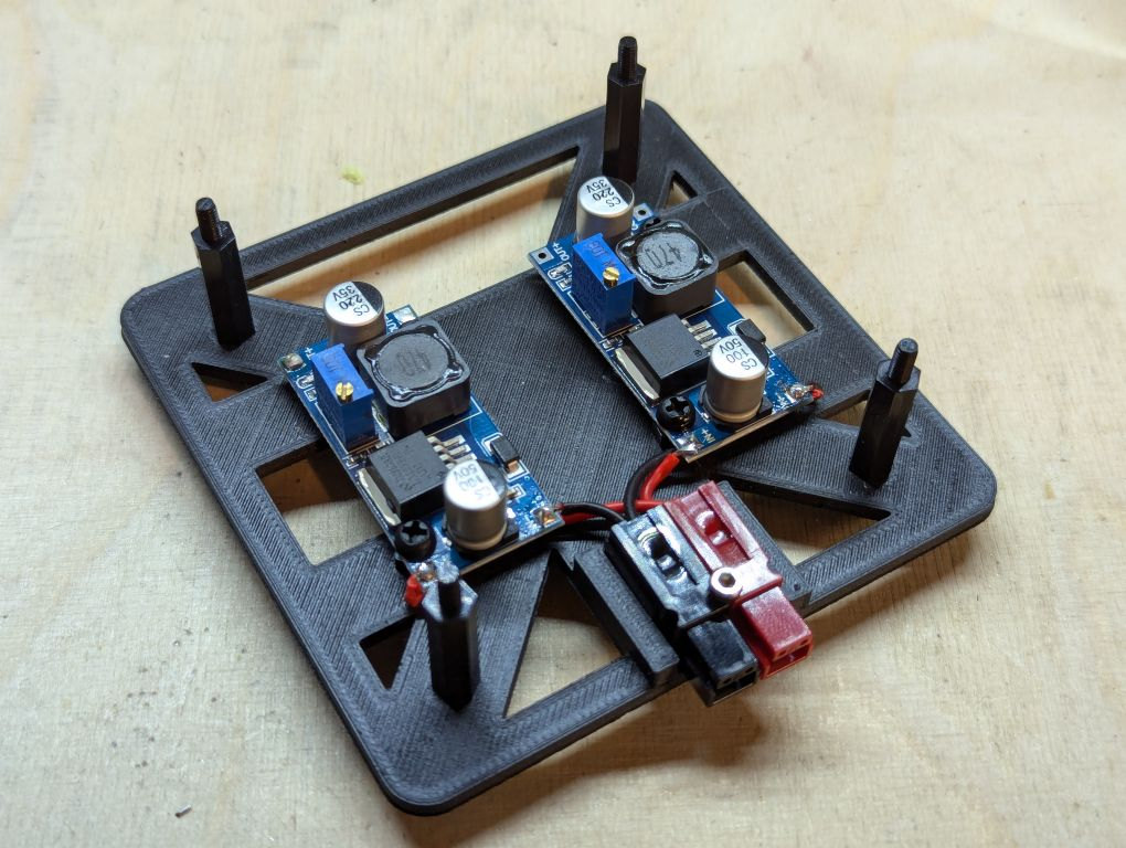
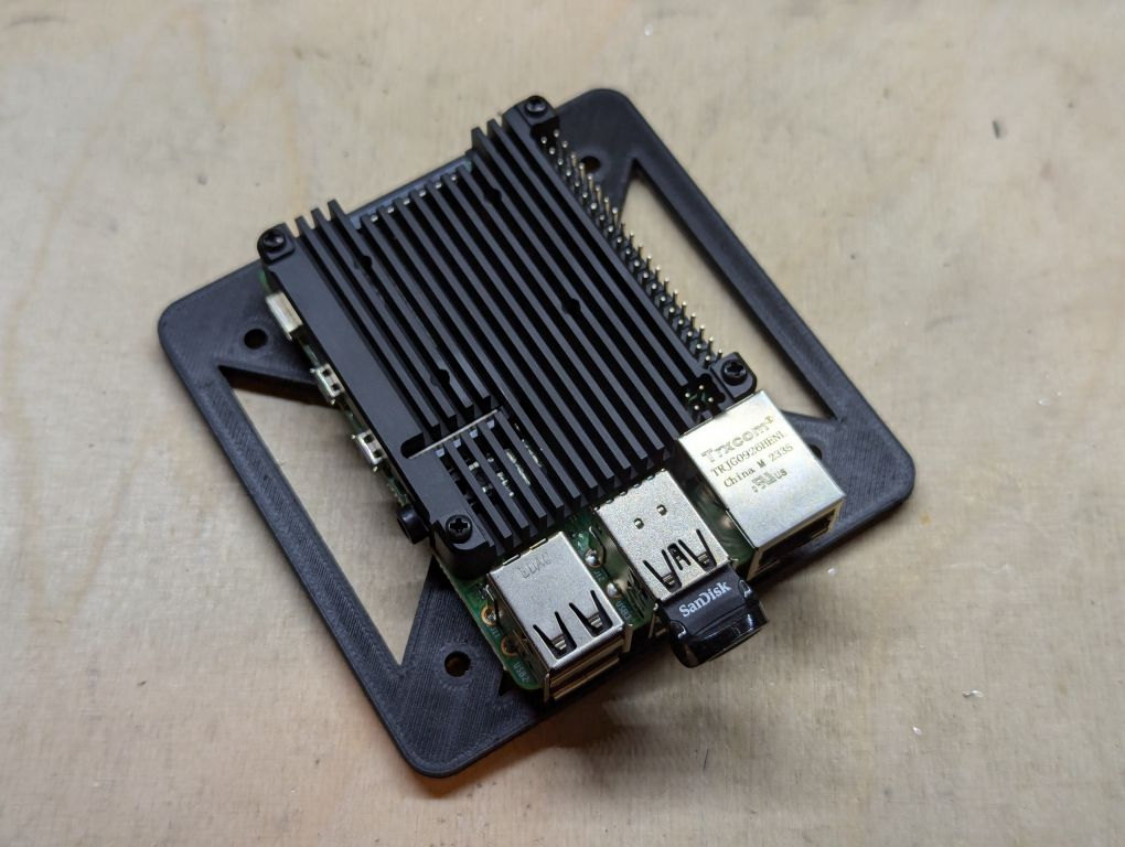
Raspberry Pi Module
The Raspberry Pi was mounted together with the NVMe module in sandwich construction on the corresponding module carrier. There was still space next to it to accommodate a buck converter, which regulates the 13.8V down to 5V for the single board computer.
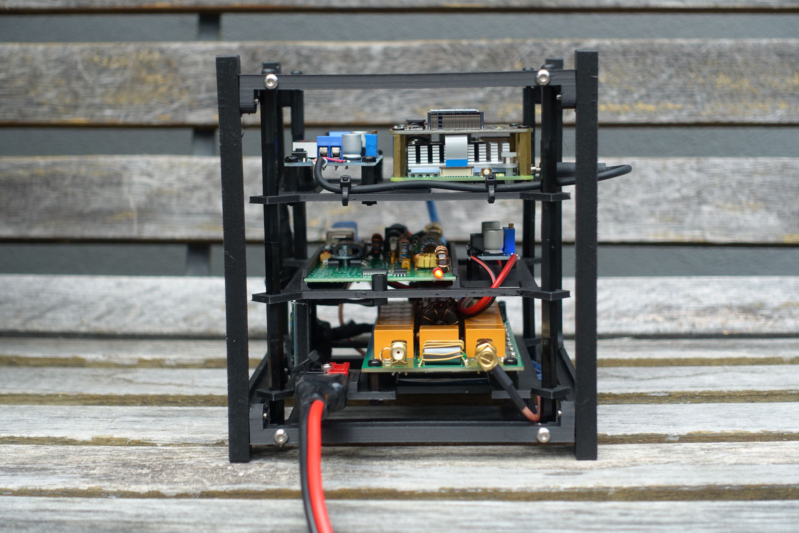
Assembly
Now the CubeSat frame was printed and screwed together with M3x10 stainless steel screws and the corresponding nuts. The three pre-assembled module supports were then installed in the frame one above the other using M3 nylon spacers so that they were screwed to the frame with four screws each at the top and bottom.
The cabling was then installed:
- A 30cm SMA to SMA coaxial cable with angled connectors to connect the ATU to the QDX
- A short USB cable to connect the QDX to the Raspberry Pi (CAT and audio)
- Three two-core cables for the power supply, each running from the Powerpole connector to the ATU and the buck converters
- Two two-wire cables from the buck converters to the QDX (hollow plug) and the Raspberry Pi (USB-C)
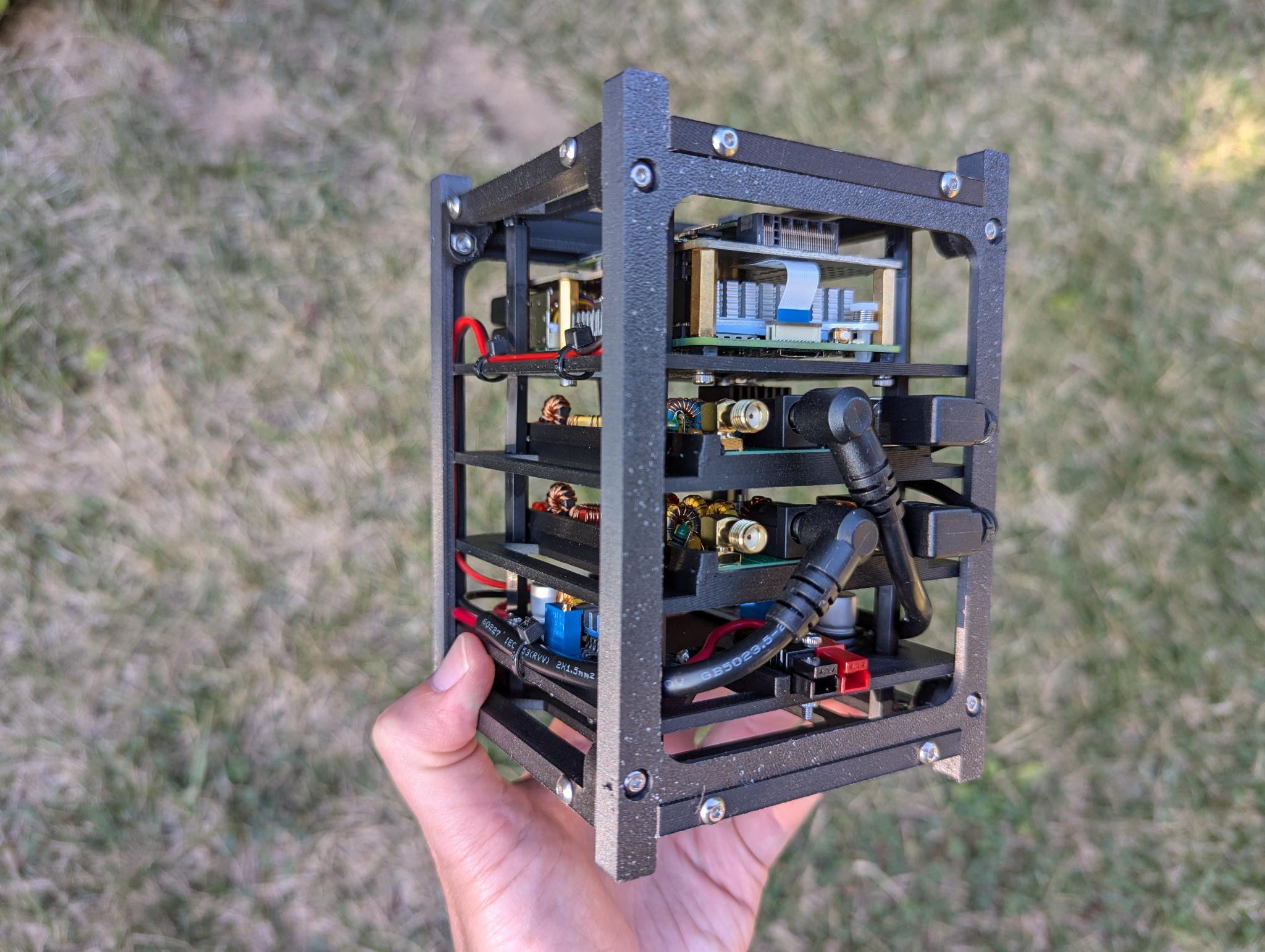
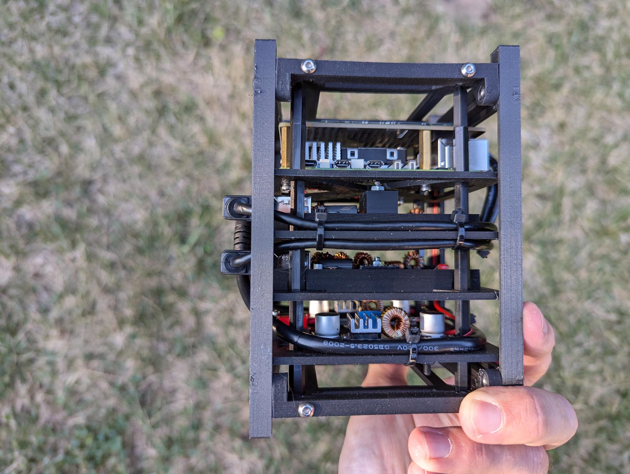
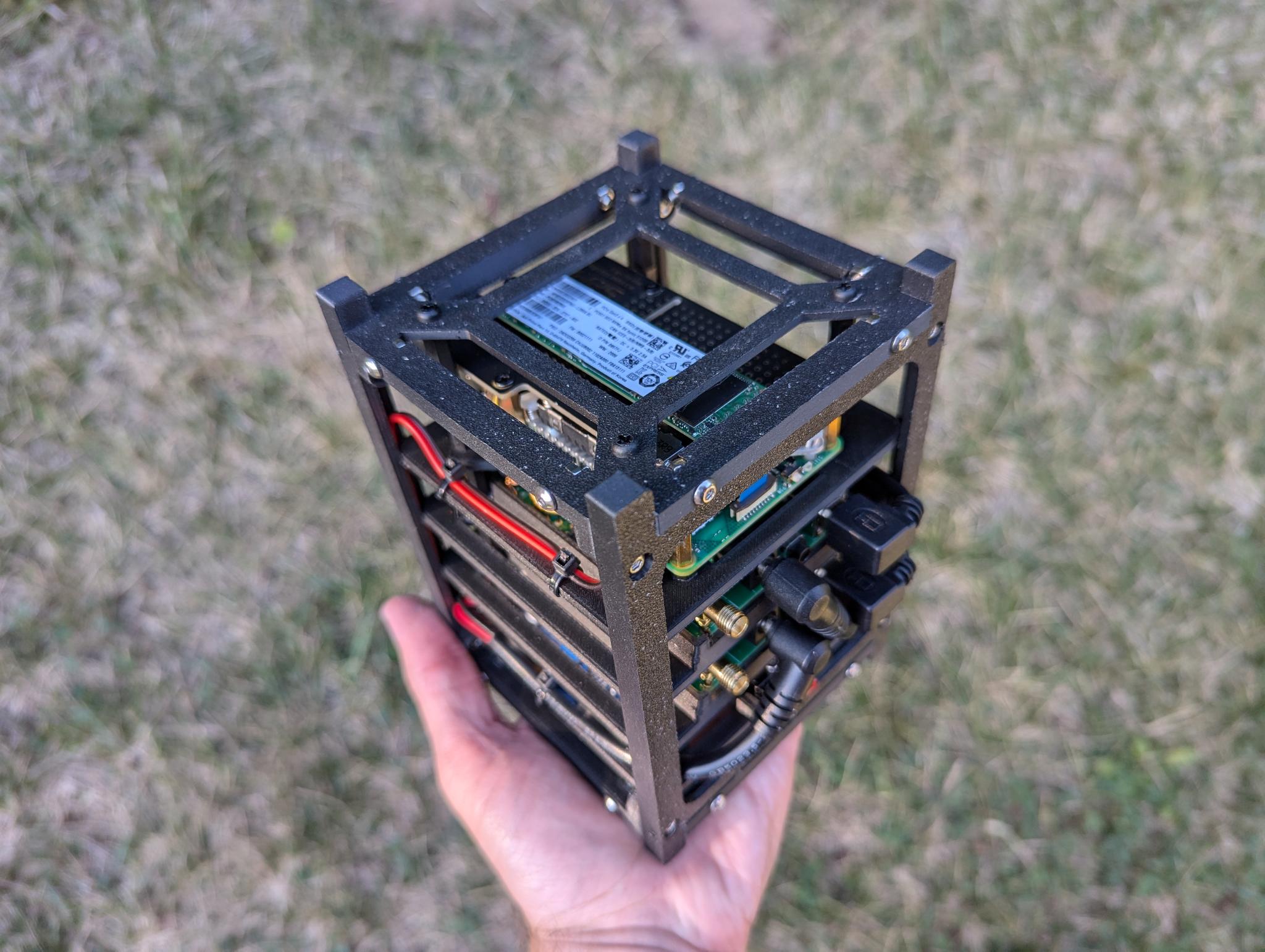
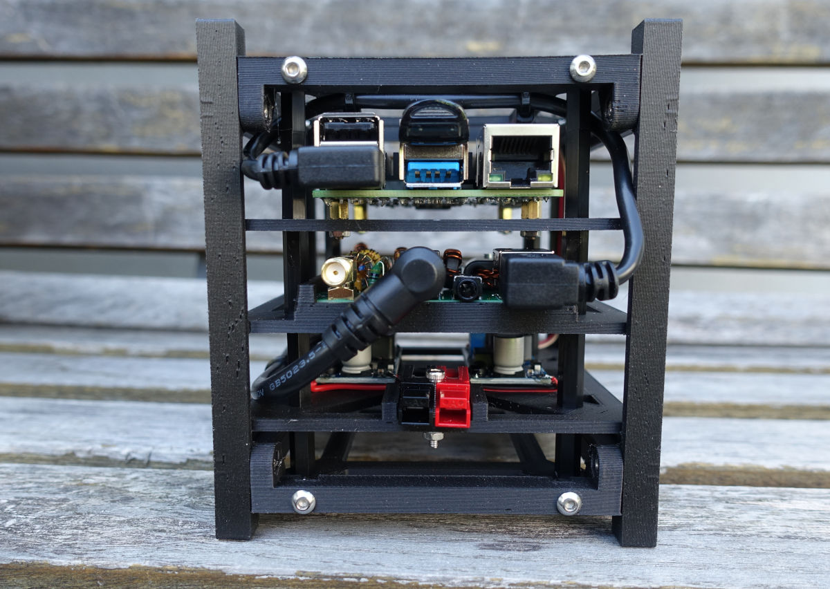
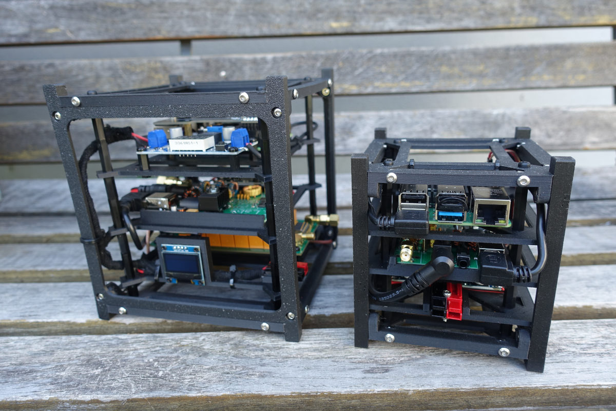
The Result
The following pictures show the finished setup:
Updates and Modifications
I am documenting all updates and modifications here in this separate post.

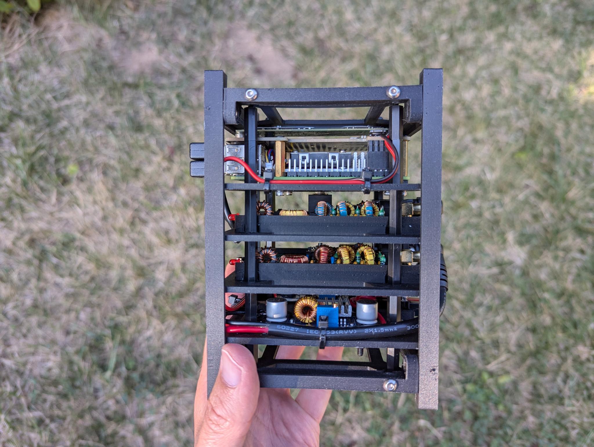

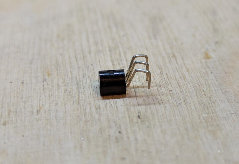
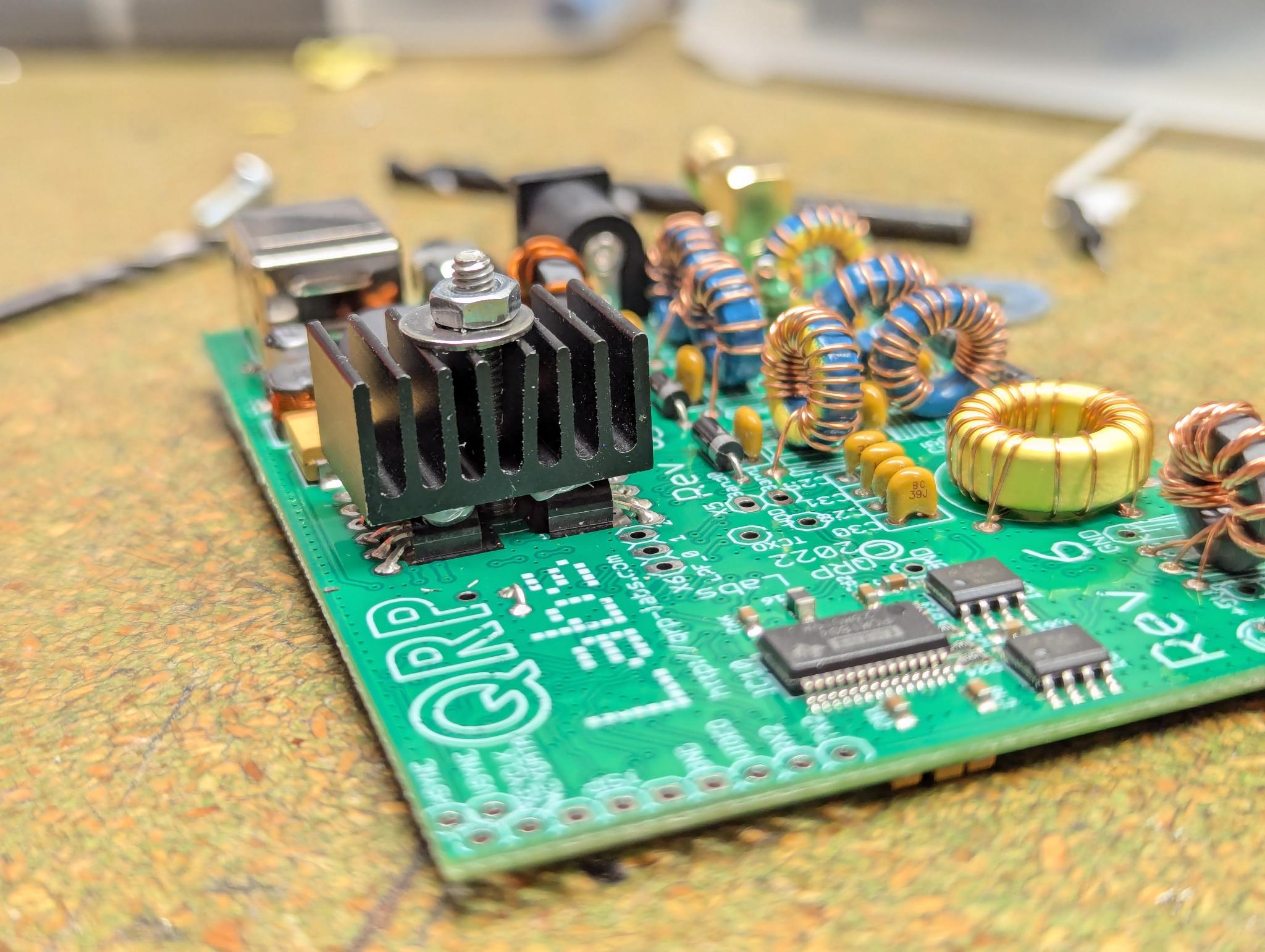 (Note: This picture shows the heat sink with the four BS170)