Reading view

There are new articles available, click to refresh the page.

Is port extension or e-delay a universal solution?

Several recent articles examined the use of s11 port extension or e-delay in some scenarios that might have surprised.

Recall that s11 port extension adjusts the measured phase of s11 based on the e-delay value converted to an equivalent phase at the measurement frequency.

It is:

  1. an exact correction for any length of lossless line of Z0=50+j0Ω transmission line;
  2. an approximate correction for a very low loss length of approximately 50Ω transmission line; and
  3. an approximate correction for some specific scenarios such as those discussed at Some useful equivalences of very short very mismatched transmission lines – a practical demonstration.

Of course 1. does not exist in the real world, but 2. can give measurement results of acceptable accuracy if used within bounds. Both departures mentioned in 2. occur in the real world, non-zero loss and departure from Z0=50+j0Ω. Provided these departures are small, port extension may give acceptable results.

Let’s analyse some example measurements based on a 10m length of ordinary RG58A/U from 1-11MHz.

Above, measurement of the first series resonance with SC termination.

Note that the curve is a spiral inwards from the outer circle, the line is not lossless.

A requirement for e-delay to work well is that phase of s11 is proportional to frequency. This plot wraps, but apart from that, the plot looks approximately linear… however scale prevents detailed analysis.

Above, measurement of the first series resonance with OC termination.

Note that the curve is a spiral inwards from the outer circle, the line is not lossless.

Again the plot wraps, but apart from that, the plot looks approximately linear… however scale prevents detailed analysis.

Let’s find a value for e-delay at 1MHz and analyse the result.

Above is adjustment of e-delay to 115ns for approximately s11 phase 180° at 1MHz with SC termination.

The phase is correct at 1MHz, but at higher frequencies, it departs. So, the assumption that this TL has phase delay proportional to frequency is invalid. If you look closely, it is not a perfectly straight line, there is a small oscillation superimposed which is a sign of Z0 error. For these reasons, e-delay correction will have error.

Above is adjustment of e-delay to 100ns for approximately s11 phase 180° at 1MHz with OC termination.

The phase is correct at 1MHz, but at higher frequencies, it departs. So, the assumption that this TL has phase delay proportional to frequency is invalid. If you look closely, it is not a perfectly straight line, there is quite an oscillation superimposed which is a sign of Z0 error. For these reasons, e-delay correction will have error.

Let’s proceed anyway and look at the error. We will connect the 50+j0Ω termination load to the end of the cable and measure with each of the e-delays above.

Above is measurement of a 50+j0Ω termination with e-delay calibrated using 100ns e-delay (calibrated to OC termination). Note that the curve is a small circle, a sign of Z0 error and a hint that actual Z0 is about the centre of the circle plotted. Note though that Z0 is frequency dependent at these frequencies for this cable, so you can’t pin a pin on the chart and say this is Z0.

Above is measurement of a 50+j0Ω termination with e-delay calibrated using 115ns e-delay (calibrated to SC termination). Note that the curve is a small circle, a sign of Z0 error and a hint that actual Z0 is about the centre of the circle plotted. Note though that Z0 is frequency dependent at these frequencies for this cable, so you can’t pin a pin on the chart and say this is Z0.

At 5.75MHz and:

  • e-delay from the SC calibration, Z=45.01+1.25Ω; whereas
  • e-delay from the OC calibration, Z=45.01-1.26Ω.

For some purposes, that might be sufficient accuracy, for others it might be unacceptable:

  • Z0 departure is more significant for lossier cables below about 10MHz; and
  • in any event loss of tenths of a dB leads to measurable error.

Conclusions

Port extension or e-delay can provide a convenient means of shifting the reference plane given suitable test fixtures, but it is subject to significant error if the underlying assumption of lossless 50Ω line is breached.

Last update: 16th August, 2024, 12:58 PM

Testing the new(to me) rig

Remember yesterday when I mentioned the latest addition to my POTA setup, the Xiegu 5105 QRP rig….

Well this morning I decided to test it out and see how much work I would have to do with setting the parameters such as mic gain, processor, to make it sound like me… I was also testing out my EARCHI 9:1 unun with a 29.5 foot random wire to see how it would play with the built in AT of the 5105.

I figured I might as well do the testing at a POTA location just in case I was able to turn the test into an activation.

For this I chose Fort Frontenac POTA CA-5303. Its fairly easy to get there via the Kingston Transit system and its also close to downtown and all the amenities I might need. In the North East corner of the picture you will notice some white lines on the ground.

They are actually the walls of what’s left of that part of the Fort. Also the only parts of the Historic Site that is open to the public.

I leaned my MFJ 33 foot mast (supporting the 9:1 and wire in the vertical configuration) up against the tree.

And then ran the COAX over to the remains of the wall and set up my radio there and started operating.

My first contact was on 7.255 with the NCS of the ECARS net. He did hear me and considering I was QRP I was pleased. He did tell me that my audio seemed hot as if I was overdriving things. Lowering my voice seemed to help.

After that I looked at POTA Spots and managed to get W2IDG and VE3FI into the log from their parks and then finished up with the NCS of the MidCars net on 7.258.. All contacts were made on 40m SSB. I tried 20 SSB and was hearing lots of stations including a POTA Activation in VO1 but no luck breaking any of the pileups.

Then I figured it was time to get home and try to re configure the radio to my liking… I turned off the Speech Processor and lowered the Mic Gain from 60 to 40. Over the next few days I will get out again and see what else I have to do to get things sounding right.

Till then

73bob

via the ARRL: Hurricane Ernesto Updates

Thursday, August 15, 2024 Midday Update:

The National Hurricane Center reports that Tropical Storm Ernesto had become a Category 1 hurricane.

A hurricane warning has now been issued for Bermuda and dangerous rip currents are likely along U.S. East Coast beaches this weekend, August 17 - 18.

Bobby Graves, KB5HAV, Hurricane Watch Net Manager, reports the net’s activation plans:

Friday August 16 

20 me...

Read more

American Radio Relay League | Ham Radio Association and Resources - Read More

Logs 15 Aug 2024

1233 2156 Radio Rock Revolution. SINPO 24432. //5880
1625 2027 Radio Torpedojager. SINPO 44433.
1629 2048 Radio Blauwe Fazant. SINPO 34433.
3940 2005 Music Wave Radio. SINPO 54444.
5846 1817 Radio Joey. SINPO 44444.
5880 2055 Radio Rock Revolution. SINPO 44433.
6280 1811 Radio Argus. SINPO 55444.
6295 1801 Mike Radio. SINPO 54444.
6303 1827 Radio Mustang. SINPO 54444.
6325L 2015 Radio Kobus. SINPO 24432.

Amateur Radio Newsline Report 2442 for Friday August 16, 2024

- STARLINER ASTRONAUTS MAY RIDE HOME ON CREW DRAGON
- HAARP RESEARCHERS SEEK HAM INPUT
- HAMS IN INDIA GIVE FEEDBACK ON RADIO RULE PROPOSALS
- NEW SHORTWAVE TRANSMITTER FOR RADIO NEW ZEALAND
- ARCTIC CIRCLE BROADCASTS TO DEBUT AS LONGWAVE RADIO
- US BUSINESS PETITIONS FOR EXPANDED USE OF 900 MHz
- TWO CUBESATS GIVE SATELLITE FANS MORE OPTIONS
- HAMS' WIRELESS TECHNOLOGY WORKSHOP ASSISTS POLICE
- WRTC OPENS BIDDING FOR ENTRY OF SPONSORED TEAMS
- WORLD OF DX
- KICKER: HAM RADIO FAMILY EMBRACES SILENT KEY'S CALLSIGN

SCRIPT

AUDIO


💾

Why did I give up the valve collection?

Some of you may remember that I used to collect valves. I started collecting when I was around 6 years old, although back then it was more to impress friends than collect. An old directly heated valve plus a Lego battery box lit my desk up at primary school. I did not start collecting in earnest until the 1990’s and launched my first online valve museum in 1999. Since then the collection grew in several directions at once, including German WW2 types, Russian Cold War types and British military and civilian types. There were specials from all over the world as well including a few Japanese WW2 ones. Valves ranged from tiny little things to a RD150YB that had to live in the garage, and a 6-anode mercury arc rectifier that was equally not allowed in the house, and for good reason too. The main collection grew to over 3,000 types, many of which had duplicates, so probably 4,000 in total. And then there were boxes of valves that did not warrant adding to the collection.

And so the collection continued to expand. While on holiday in the US friend in the US was discussing collecting trends with me and another collecting friend and said he collected US antique types, others collected microwave types and, pointing at me he said I collected everything and there is nothing wrong in that. But it made me think what exactly is my interest. And so I decided to concentrate on what I found most interesting – British military types, mainly in the CV, and A, N and V military series. The collection included a number of CRTs as well and eventually took over the whole garage.

I decided then to concentrate solely on CV types and trimmed the collection to 1,500 types, again with duplicates taking the collection to over 2,000 valves. Of the remainder many were sold and many hundreds went to the National Valve Museum which was nearly as old as my own.

Eventually though three things happened. First, it was becoming increasingly difficult to find new additions. Second, the website was now seeing fewer and fewer actual hits (as opposed to search engine spiders), and, most importantly I realised it had become an obsession. Time to quit. I also came to the realisation that I had an awful lot of valves in lots of boxes and I never even looked at any once they went into a box.

So I decided to close the website and sell off anything I could, donating the remainder to the National Valve Museum. The website was essentially converted to flat HTML files with none of the database behind them and taken over by a member of the BVWS. Of course, all praise to them for doing that, but none to me for all my years of work. Par for the course. In the past 20 years I received just a handful comments thanking me for providing the photographs and information about the collection. I was somewhat surprises at the screams when I announced the website was to close. Of course, I did not make the website for that, I did it because I thought people might actually be interested, and they clearly were back at the turn of the millennium but times change.

I was fortunate that someone local took many of the CRTs and a bunch of valves as well. Of the rest, a few hundred are destined for friends in Australia, the Netherlands, Belgium and Italy but the logistics are going to be a nightmare. Several hundred have found new homes here in the UK. Of the thousands left these went to the National Valve Museum with the more mundane radio and TV types being scrapped as no-one wanted to come and get them. I am keeping many of the early magnetrons for later sale, and some of the more decorative valves for, well, decoration!

There are still several boxes and a cupboard full of valves and they are destined to be scrapped. Selling on eBay as an individual has become more and more complex over the years so I will rarely sell there. As no-one was interested in paying me a visit to take them away they will end up in the dump.

At its height the collection took over half the workshop and half the garage. Once trimmed down to the CV types it was still half the workshop. Now it is all under one bench and I have more space to set up the various tools that have been sidelined for years and actually get back to working on the house.

Hurricane Ernesto Updates

Thursday, August 15, 2024 Midday Update:

The National Hurricane Center reports that Tropical Storm Ernesto had become a Category 1 hurricane.

A hurricane warning has now been issued for Bermuda and dangerous rip currents are likely along U.S. East Coast beaches this weekend, August 17 - 18.

Bobby Graves, KB5HAV, Hurricane Watch Net Manager, reports the net’s activation plans:

Friday August 16 

  • 20 me...

Solar Cycle 25 Producing Record High Sunspot Numbers

By: Frank Donovan, W3LPL

Editor’s note: This article was written earlier in the week. The latest measurements show even higher numbers. See this week's K7RA Solar Report in The ARRL Letter for latest information. 

Record High Solar Cycle 25 Solar Maximum Sunspot Numbers Have Improved HF Propagation Since Mid-July and Possibly Bringing Worldwide 6 Meter F2 Propagation This Fall.

According to the NO...

Radio Galaxy Finland eQSL


A surprise in my inbox today after six weeks an eQSL arrived confirming my reception of the Finnish pirate Radio Galaxy. I logged the station with a weak signal in SW England but it was enough to catch an ID and send off a report. Many thanks DJ MegaHertz.

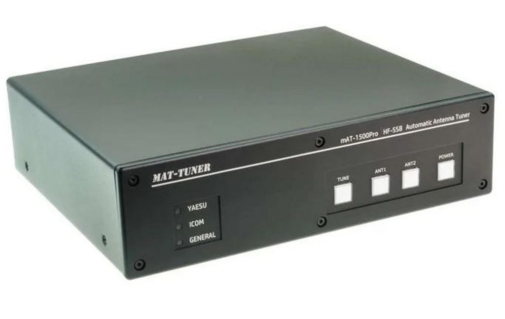
New Products Spotlight: mAT-TUNER mAT-50 and 1500PRO Automatic Antenna Tuners (video)

Vibroplex, which first manufactured and sold its signature Morse code “bug” key back in 1904, is the longest continually operating ham radio equipment provider on the planet, but that doesn’t mean the venerable company doesn’t have more than a few new tricks up its well-worn, rolled-up sleeves.

DX Engineering’s Rod Ehrhart, K8RR, caught up with Scott Robbins, W4PA, Vibroplex’s owner since 2009, at Dayton Hamvention 2024 to discuss the mAT-TUNER line of automatic antenna tuners, which the Knoxville, Tennessee-based company has distributed in the U.S. since 2019. Watch the video below:

Scott, W4PA, highlights two new mAT-TUNER offerings—mAT-50 Automatic Antenna Tuner and Coupler Packages and the 1500PRO Automatic Antenna Tuner, both available along with the entire mAT-TUNER lineup at DXEngineering.com.

The multipurpose, 1.8-54 MHz mAT-50 Automatic Antenna Tuner comes with either an Icom, Yaesu, or Kenwood coupler and corresponding control cable. This remote tuner has the capability of matching a variety of impedances and antennas including long-wires, dipoles, verticals, Yagis, whips, and virtually any coax-fed antenna. It features a maximum input power of 120W SSB/60W Digital.

Automatic Antenna Tuner and Coupler Package
(Image/DX Engineering)

Install the sturdy, weather-resistant tuner outside near the antenna. Then install the coupler inside near the transceiver to provide power for the tuner and control its operation. The tuner does not require a control cable between the remote tuner and coupler, making installation simple. The only required connection between the antenna tuner and coupler is one 50-ohm coaxial cable. Advanced technology employed in the tuner delivers stable performance and excellent anti-interference capabilities for convenient one-key tuning.

The mAT-50 can also be used as a universal tuner for all transceivers if a mAT-50-Y or mAT-50-M coupler is connected to an external DC power supply (not included) and a control cable is not installed. You can then operate the tuner manually.

The mAT-1500PRO Automatic Antenna Tuner is an upgraded version of the original mAT-1500 tuner. Improvements include reduced weight, high- quality housing, and additional interfaces for Yaesu, Icom, and Kenwood transceivers and their corresponding operating modes. This allows the tuner to be controlled directly from the transceiver, reducing the need for manual operation.

Module for an Automatic Antenna Tuner
(Image/DX Engineering)

In addition, two antennas can be connected simultaneously, and the corresponding buttons for switching (in receive mode) are placed on the front panel for easy access. Other features include:

  • Designed for modern transceivers with a frequency range of 1.8-54 MHz
  • Rated for up to 1,500W SSB/800W Digital
  • 16,000 memory locations
  • Fast tuning—found values for a frequency are stored in the memory, enabling adjustments as quick as 100ms
  • Loop-through of the PTT line makes it possible to loop in the power amplifier behind the tuner. The tuner interrupts the PTT line to the power amplifier during the tuning process. This avoids tuning with high power, greatly reducing the possibility of damaging the tuner relays.
  • 6 to 1,000 ohms tuning range, which corresponds to an SWR range maximum of 10:1. This allows it to match all coax-fed antennas such as a G5RV with a balun at the transition between two-wire ladder line and coax cable, but also a wideband vertical antenna designed for the rated power.

See all mAT-TUNER automatic antenna tuners and accessories at DXEngineering.com, including the MAT-Y200 for Yaesu transceivers, the MAT-705PLUS for the Icom IC-705, and the MAT-180H for select Icom and Kenwood transceivers.

The post New Products Spotlight: mAT-TUNER mAT-50 and 1500PRO Automatic Antenna Tuners (video) appeared first on OnAllBands.

ARRL Urges Protecting the Amateur Radio 902-928 MHz Band

The Federal Communications Commission (FCC) accepted for public comment a Petition for Rulemaking filed by NextNav Inc., a licensee in the 900-MHz Location and Monitoring Service (LMS), to completely reconfigure the 902-928 MHz band and replace the LMS with high-powered 5G cellular and related location services.

The FCC Notice requested comment on the effects that NextNav’s proposals would have ...

❌