❌

Normal view

There are new articles available, click to refresh the page.
Before yesterdayVU2JXN Station log

50db sampler

23 December 2023 at 12:44

Motivation

If you want to measure fairly high power or see the spectrum in a spectrum analyzer, you will need to attenuate the output. Normally, spectrum analyzers can only accept a very low power signal as its input. The other factor to remember is that the power is the average power over the entire bandwidth of the spectrum analyzer. You may be watching a part of the spectrum. But there may be harmonics or other signals in other part that is outside your "view port" and if you add all that power together and if that exceeds the specification, the spectrum analyzer would get damaged. Seasoned RF engineers say that one should never terminate a power source with a spectrum analyzer. It is mostly guaranteed to damage the unit.

Using an attenuator is also pretty hard. Let us say you want to attenuate 100W into say 100mW. That is a factor of 1000. The power rating of the resistors in the attenuator is also a factor to consider.

Solution

We will need some kind of a "tap" or a "sampler" of the input power. The principle is somewhat similar to the directional coupler in a transceiver.

I followed this design by Don Jackson, W5QN. There are other designs by W7ZOI and others. TinySA website also links to a design. But I chose Don's design, because it had some analytical explanations that I can follow and also because a friend of mine had built it in the past.
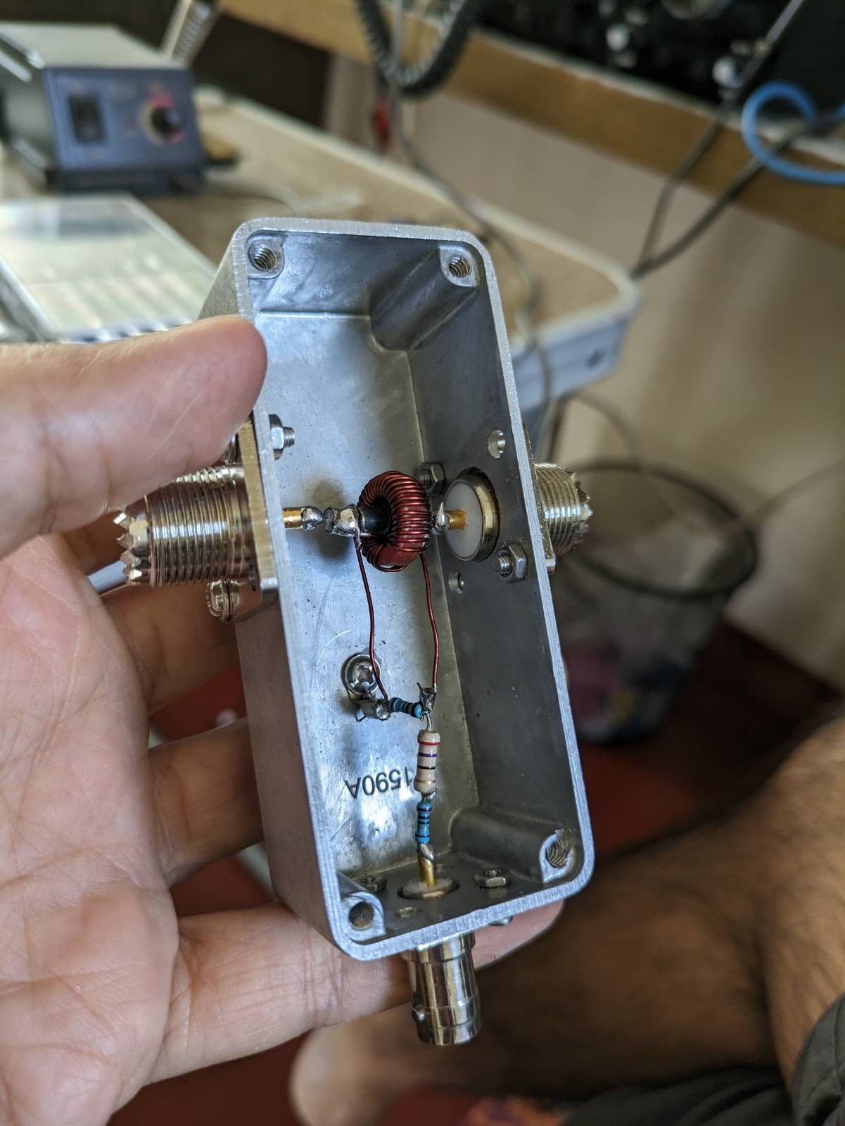
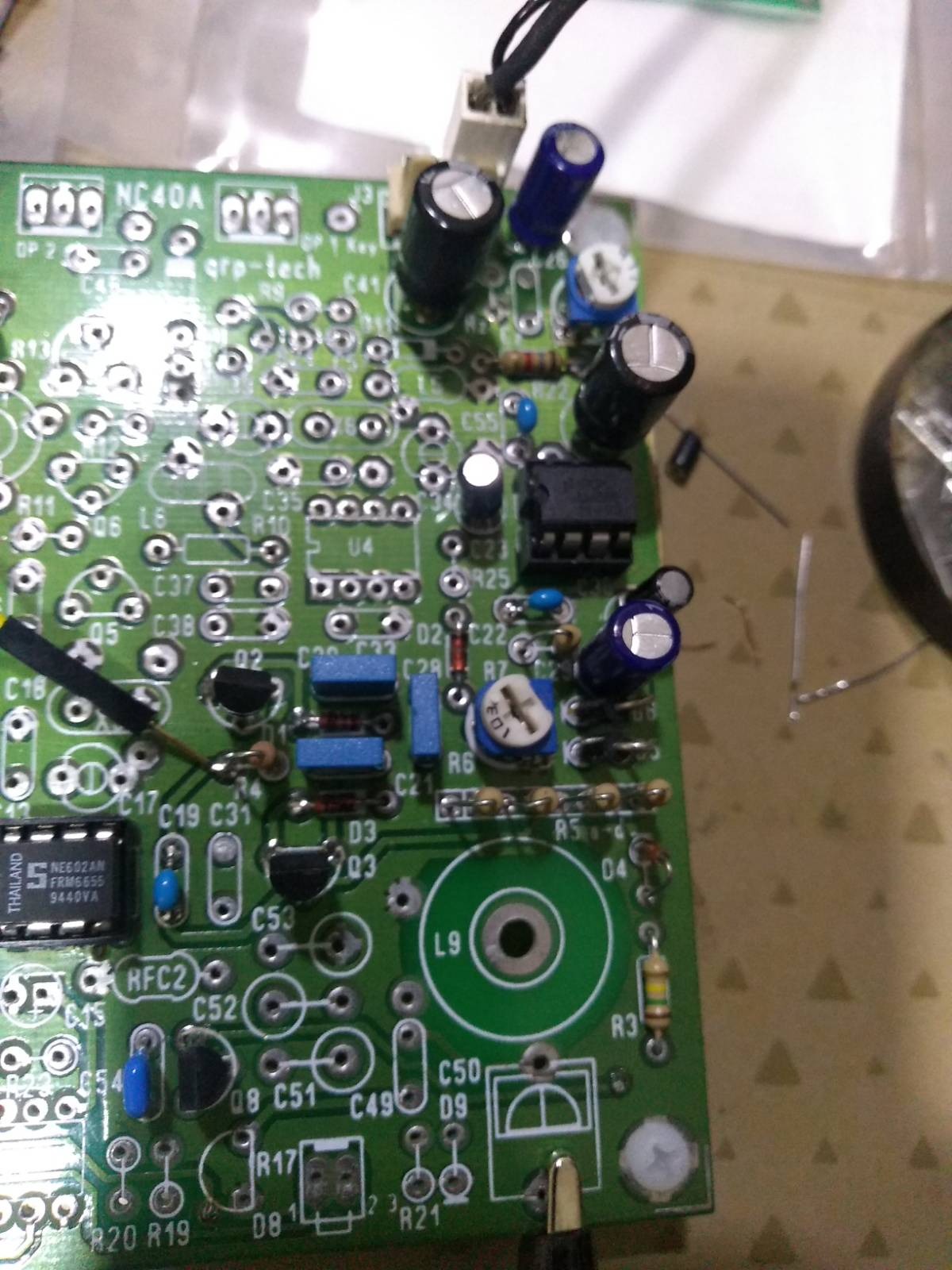
Build pictures.

I used a cheap box (hammond 1590a clone from ebay).

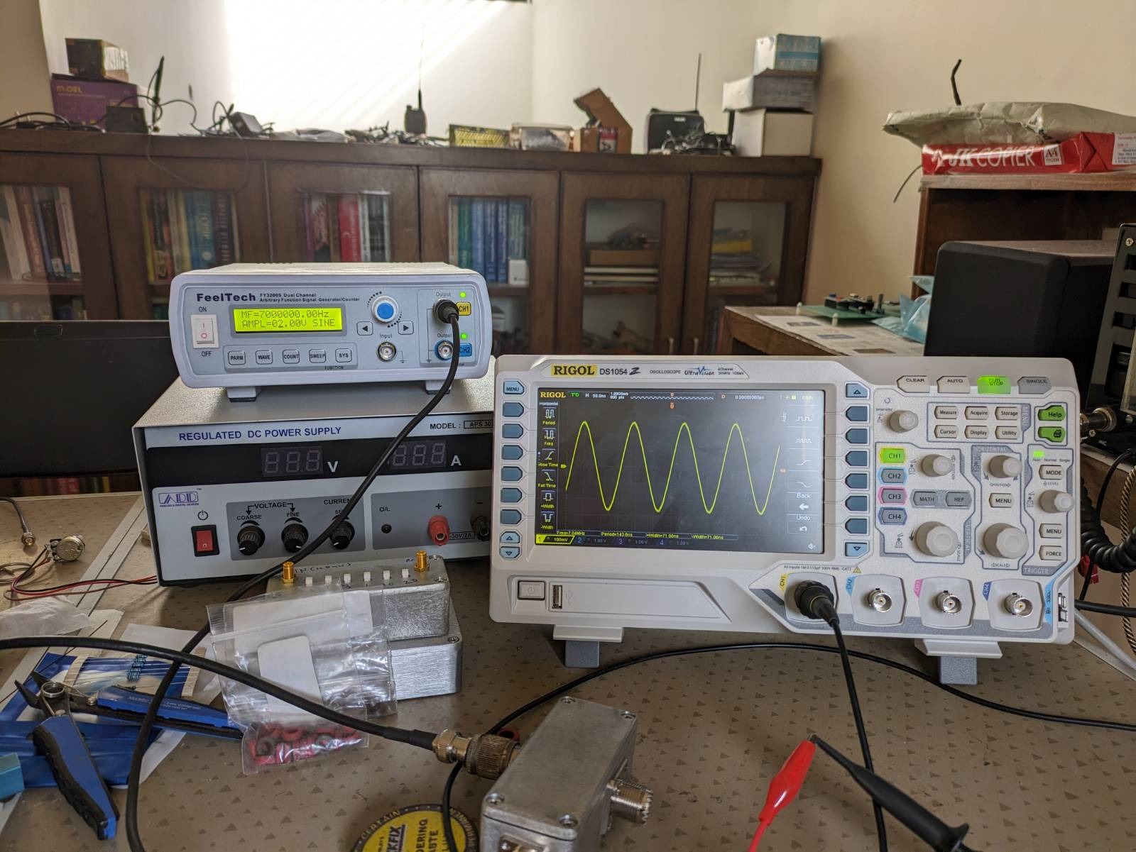
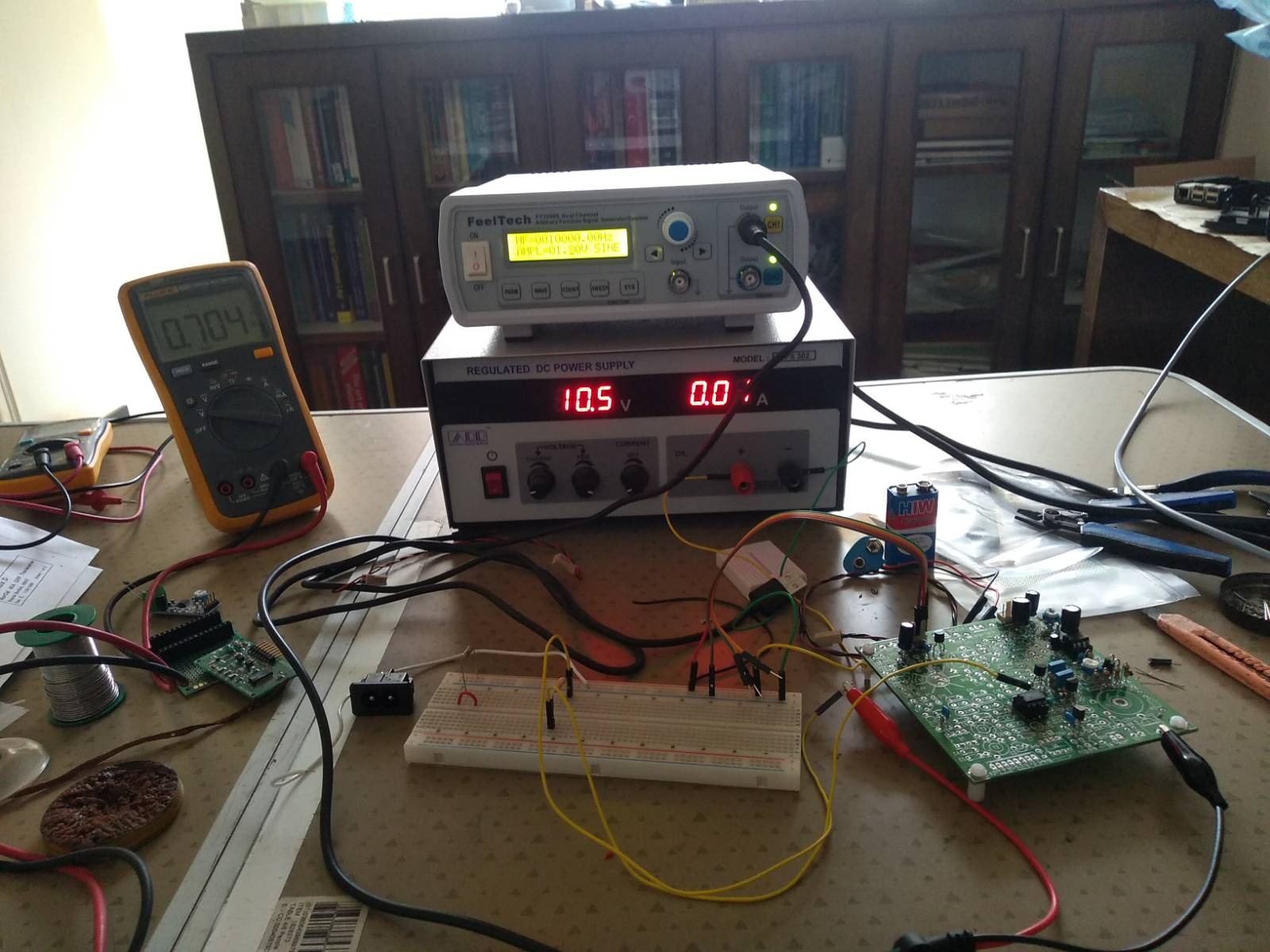
Unfortunately, my cheap signal generator can only show and change level in volts. In the RF world, everyone use dbm. Web calculator to the rescue. I usually use this calculator. 10dbm is 2V peak-peak.

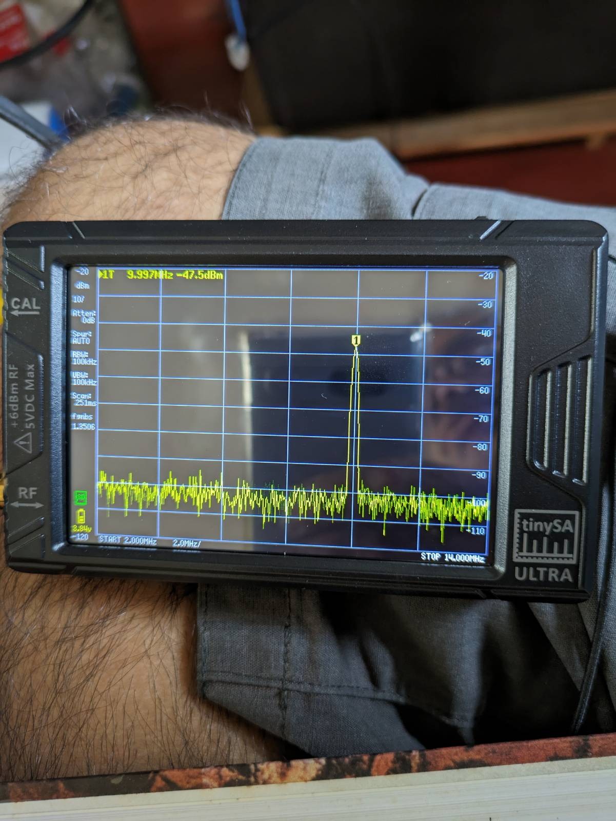
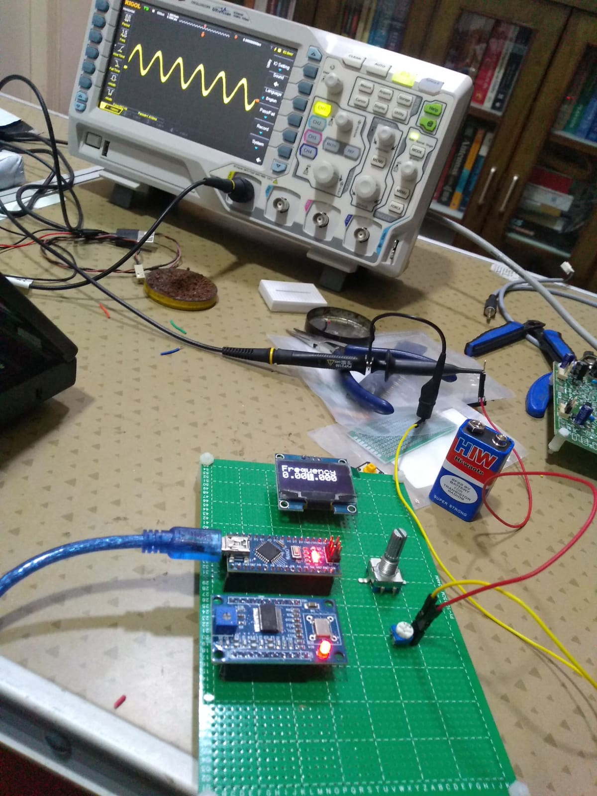
Output port is connected to a dummy load. Sampler output goes into TinySA.

input signal - 10dbm inside the sampler tinySA output - 57.5db attenuation

Bench updates

16 November 2023 at 13:34

Been silent for the past few months. Have been busy at work. But the bench has been active. A couple of months back I found out that the 10m output from my radioberry based transceiver is too low (~10W). The amp (MRF101 based) can easily deliver 100W on 10m. Upon closer inspection, I found that the LPF (homebrew) was absorbing all the power form the amplifier. The LPF cutoff was a bit too early and was going steep in the 10m band. Same filter also works when the rig is in 15/12m and it worked fine there.

The filter was redesigned with the excellent Elsie software and old components were removed and replaced with new values. Everything is fine now. I get about 60W. I think the reduction is probably because the radioberry itself has a slightly reduced power output on 10m (just a couple of dbm). I have an attenuator going into the input of a pre-amplifier and that may have reduced the power by additional 3db. I haven't bothered to correct it. 60W is definitely "good enough" for me at the moment.

Norcal 40a: Waiting for components

28 June 2023 at 11:23

One rule that I learn painfully every time I build anything off late is that one has to take some time at the beginning of the project and gather all the parts all at once before beginning to build the project.

Right now, I am waiting for a measly 50pf trimmer capacitor to build and test the next stage of the Norcal 40a. :-( And I end up paying for postage twice, just because I missed ordering the part when I ordered for parts from a source the first time. This is a reminder to myself that I shouldn't do this mistake again.

Norcal 40a: Phase 3 (AGC)

22 June 2023 at 15:38

I just completed the Norcal 40a AGC circuit. I wrote something about it a month back. Since then, I have been reading "The electronics of Radio" on and off, pretty much the same set of pages again and again, trying to understand what is going on.

I even prototyped the AGC circuit on breadboard.

But I did not get much insight from it. The bias voltages were checked, V-gs and V-ds were measured to verify that the JFETs were operating in the variable resistance region of JFET. But that was not the case. The insight was when I realized that the circuit in the book assumes that the previous part of the circuit (i.e. the product detector) was already populated because at the point AF2, a voltage comes out via pin 4 of U2 (internally, Pin 4 is routed to 8v via a 1.5k resistor).

With that failed experiment, I decided to go ahead and populate JFET and the biasing scheme and the two schottky diodes into the board. The arrangement needs matched resistors. I was using 2.2M 5% tolerance resistors. Also my board does not have any via so those parts whose legs act as a via also needs to be installed. This is the test setup. The input signal from the function generator to JFET is via a 300k resistor.

I had a missing via and once that was found and the component installed and the U2 also installed, the bias measurements on JFET's legs were all as expected. The problem 32 measurements were performed.

V-c (DC) V-out (rms) 
7.09     1 
7.1      1 
5    1 
4.6      1 
2.57     0.23 
3.11     0.98 
1.6      0 
2.49     0.086 
2.7      0.62 
2.89     0.956

This is a nice curve that switches from an audio voltage of 0v to Vcc pretty quickly at a control voltage around 2.5v.

I then went ahead and installed the two capacitors C29 and C30. These capacitors are the ones that puts the "A" (automatic) in AGC. I did a handwavy test by increasing the input signal's amplitude and observing the audio output connected to a speaker by ears. At low input signal magnitude, increasing the input increased the output volume. However after a point, increasing the input signal magnitude did not significantly increase the audio volume, it more or less remained a constant.

On to the next phase..

Feeltech signal generator

20 June 2023 at 05:58

I wrote about the recent signal generator purchase. The unit has a known problem, the earth is floating and the DC side "ground" reference is coupled from the AC side via a capacitor. If you happen to touch the reference points on the probe BNC connectors, you get an electric shock! About 100V ac on those points..

So, I bought a 3-pronged AC female connector and filed the cabinet a bit and fitted it and wired the common to the proper earth. A proper fix would be to replace the power supply itself. Feeltech says they are replacing the powersupply soon..

AD9850 based signal generator

8 June 2023 at 14:50

I built a signal generator based on ebay AD9850 card and a junk box encoder and an OLED 128x64 display. The code is mostly from Dean, KK4DAS signal generator. Some changes were done for display change etc. But the pins etc are more or less the same.

I noticed that when I increase the frequency, the peak-to-peak voltage reduces. The scope is a 50MHz scope. It could be that the frequency response is falling off or may be the probe is not good. But 50MHz could be the 3db point. So, there is something else going on. I will have to investigate what is going on...

I am also powering the unit with the USB from the laptop. That is awkward. I would like this to be a standalone unit. So, wiring up a power circuitry is the next in the agenda.

My code is available here. Next step is to use it to do the AGC experiments for Norcal 40a.

OLED displays

23 May 2023 at 15:52

There are cheap (~ Rs.300 =~ US$4) OLED displays available, but beware, there are at least two types of them and they even have same I2C addresses. However, if you use library for one and try it on another type, you get garbage on the screen.

These are the two types I am aware of:

  • SH110x (SH1106/7)
  • SSD1306

Some are SPI based, some are I2C based. They come with 4-pin vs 7-pin, Colour vs Monochrome vs yellow/blue etc etc. Some say, it cannot be powered from Arduino's 5V output. However, OLEDs are pretty lean on power, so my experience so far is that they work just fine with Arduino's power out and does not need dedicated Vcc.. For libraries with Arduino, I use Adafruit's libraries. They have separate SH1106 and separate SSD1306 libraries.

❌
❌